 |
|||
|
|
|||
|
Page Title:
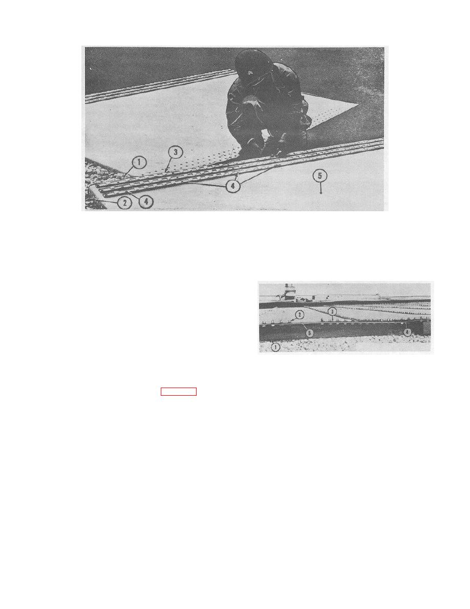
Figure 8-23. Assembling gaskets, channels, and bolts |
|
||
| ||||||||||
|
|
 TM 5-5430-209-12
1.
STAVE JOINT CHANNEL
2.
STRIP GASKET
3.
BOLT
4.
OPEN BOLT HOLE
5.
STAVE
ME 5430-209-12/8-23
Figure 8-23. Assembling gaskets, channels, and bolts.
(2) Insert -by-1 inch bolts (3) through stave
joint channels (1), stave (5) and gasket (2) in that order.
Omit one bolt in each row, about 8 inches from the
bottom of the stave and other bolts at about 2-foot
intervals, so that drift pins can be inserted to aline
staves with one another before bolting them together.
d. Preparing Outer Edge of Tank Bottom. Since
channels are not used with bolts inserted through the
chime (outer edge) of the bottom, it must be raised to
1.
LUMBER
provide clearance to insert and tighten the bolts
2.
BOLT
3.
STRIP GASKET
following installation of the first ring staves.
4.
WEDGE GASKET
(1) Raise the chime and block it with short lengths
5.
BOLT HOLE
of 3-by 3-or-4- by 4-inch lumber (1, fig. 8-24) under
ME 5430-209-12/8-24
each bottom section. about 6 inches in from the outer
edge.
Figure 8-24. Raising and preparing outer edge of tank bottom
8-13
|
|
Privacy Statement - Press Release - Copyright Information. - Contact Us |
