 |
|||
|
|
|||
|
Page Title:
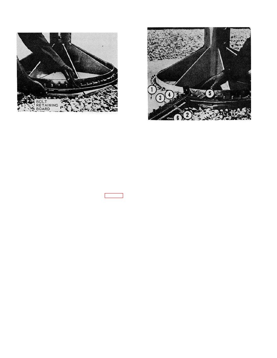
Figure 8-3. Positioning the bolt retaining boards |
|
||
| ||||||||||
|
|
 TM 5-5430-209-12
ME 5430-209-12/8-3
1.
BOTTOM ADAPTER PLATE
Figure 8-3. Positioning the bolt retaining boards.
2.
BOLTING CHANNEL
3.
LAP JOINT BOLT
8-2.
Bottom Adapter Plate
4.
STRIP GASKET
a. General. The bottom adapter plate consists of
5.
WEDGE GASKET
two semicircular, flat, steel plates. The two plates are
6.
BOLT RETAINING BOARD
attached separately to the center support base and
ME 5430-209-12/8-4
joined together by bolted lap joints. The tank bottom
plates are attached to the outer circumference bolting
Figure 8-4. Installation of first half of bottom adapter
circle.
plate.
b. Installation.
(2) Place bolting channel (2) under the joining
edge of adapter plate (1). Insert lap joint bolts (3)
(1) Set bottom adapter plate (1, fig. 8-4) in
through all except the last bolthole on the outer
position on the center support base bolt flange.
circumference of the plate and channel.
8-2
|
|
Privacy Statement - Press Release - Copyright Information. - Contact Us |
