 |
|||
|
|
|||
|
Page Title:
Section V. ASSEMBLY AND INSTALLATION OF TANK ACCESSORIES |
|
||
| ||||||||||
|
|
 TM 5-5430-209-12
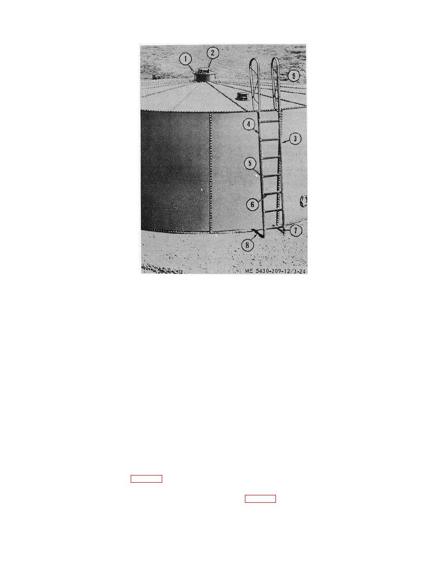
1.
MANHOLE COVER
2.
EMERGENCY VENT
3.
ACCESS LADDER RAIL
4.
ACCESS LADDER RAIL
5.
BOLT
6.
LADDER STEP
7.
LADDER BRACE
8.
LADDER BRACE
9.
HAND RAIL
Figure 3-24. Access ladder installed.
Section V. ASSEMBLY AND INSTALLATION OF TANK ACCESSORIES
3-17. Emergency Vent
3-18. Manhole Air Intake
a. General. The emergency vent consists of a one
a. General. The manhole air intake consists of a
piece, flanged, round, cast steel body fitted with lugs for
one-piece, round flanged, sheet steel dust restrictor; a
a hinged vent. The vent is a one-piece, round, cast steel
one-piece, round, fabricated, steel bar inside screen
body fitted with a lifting handle and hinge lugs. The vent
ring; and a copper insect screen.
comes attached to the flanged body hinges and seals
b. Installation.
(1) Wrap insect screen around inside screen
the deck opening.
ring. Join screen ends with copper wire.
b. Installation.
(2) Install an outside screen ring at top and
(1) Place manhole cover gasket over
bottom of insect screen to hold it in place. Make sure
boltholes at opening in cover (1, fig. 3-24). Insert 1/2-by
screen is not knocked out of position. Tighten the bolts.
11/2-inch bolts through 2-bolt-hole channels. Work
(3) Install screen ring on top flange of dome
through the 8-inch hole, and insert bolts through cover
(2, fig. 3-23).
and gasket.
(2) Install vent (2) over the bolts.
(3) Install nuts on bolts and tighten.
3-21
|
|
Privacy Statement - Press Release - Copyright Information. - Contact Us |