 |
|||
|
|
|||
|
Page Title:
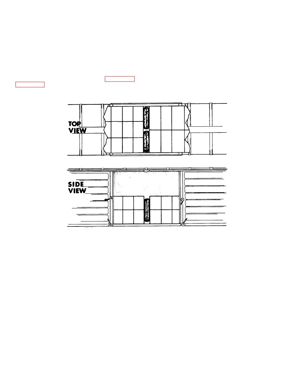
Figure 3-45. Single void pneumatic dunnage bracing pattern. |
|
||
| ||||||||||
|
|
 TM 38-400/NAVSUP PUB 572/AFMAN 23-210 MCO 4450.14/DLAM 4145.12
depending on the cargo load characteristics, hence,
voids and configurations.
Note that dunnage
arrangement must be designed to secure the entire
what was a 12-inch void may finally measure 14 to 18
inches.
lading.
Buffer boards (may be of various types
depending or lading features) should be inserted when
(3) For load configuration adaptable to
rough surfaces of load may puncture or abrade the
pneumatic dunnage use, each conveyance with a void
pneumatic dunnage units, or when pressure of the
space of approximately 12 inches after cargo loading
inflated units may damage the cargo, or where the load
(across width of conveyance) can accommodate
faces offer a pattern that would be difficult to stay
positioning of at least one unit of pneumatic dunnage or
without buffers. These figures depict either disposable
a row of the units to restrain the cargo. Figures 3-45
or reusable units.
be used to adapt pneumatic dunnage to the various load
Figure 3-45. Single void pneumatic dunnage bracing pattern.
3-79
|
|
Privacy Statement - Press Release - Copyright Information. - Contact Us |