 |
|||
|
|
|||
|
Page Title:
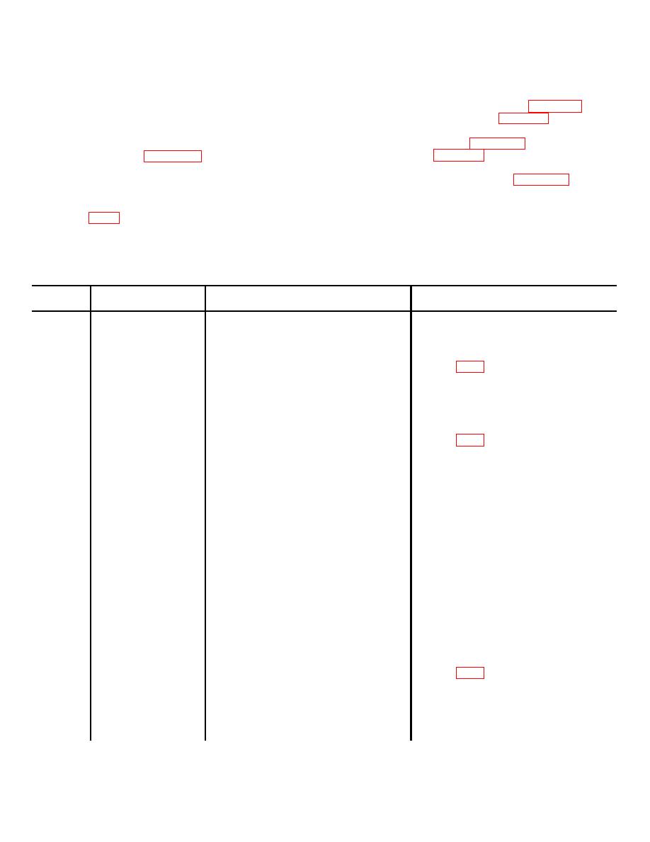
Table 7-5. Troubleshooting Monitor Control Panel SB-2600/G |
|
||
| ||||||||||
|
|
 TM 32-5895-227-14&P
units, connectors, switches, relays, and associated
7-10 TROUBLESHOOTING SB-2600/G.
wiring.
a. General. Perform the procedures indicated
(3) A single-station position requires pin-to-
below for sectionalizing, localizing, and isolating trouble
pin wiring on MX-7142/G as shown in figure 6-4 and is
to a particular circuit in the Monitor Control Panel SB-
similar to the connector wiring in figure 6-4.
2600/G (MWO 32-5895-227-15-1).
(4) A multistation position requires wiring on
b. Diagrams.
MX-7143/G as shown in figure 6-4 and is similar to
(1) The recorder (monitor and control)
connector wiring in figure 6-4.
position is shown in figure 7-6. This cable diagram
indicates the proper connector cabling required to
perform maintenance functions established with the SB-
trouble symptoms, the probable troubles, and the
2600/G.
corrective actions to be taken.
(2) The wiring diagram for the SB-2600/G is
shown in FO-8. This diagram indicates a complete
electrical means of performing maintenance on this unit.
It consists of power supplies, audio volume compression
Table 7-5. Troubleshooting Monitor Control Panel SB-2600/G
Item
Trouble symptom
Probable trouble
Corrective action
number
1
No power indication.
Burnt fuse
Check fuse F-1 located at rear of
SB-2600/G. Remove and replace
defective fuse.
Defective PS2
Refer to FO-8. Check 115 Vac input at
TB-5. Check for 24 Vdc at positive side
of 2C2. If no output, power supply is
defective. Remove and replace faulty
PS2 component as required.
2
RCVR 1 and RCVR 2
Defective power supply PSI
Refer to FO-8. Check 115 Vac input at
monitor positions
TB-5. Check for 26 Vdc at positive side
inoperative.
of C3. If no output, power supply is
defective. Remove and replace faulty
PS1 component as required.
Defective amplifiers No. 1 and No. 2
Interchange amplifier No. 3, No. 4, or
No. 5 with defective positions. Remove
and replace faulty component on
amplifier.
3
Inability to monitor
Defective monitor switch (S1) or (S2)
With monitor switch held in closed posi-
RCVR I or RCVR 2.
tion, check for 24 Vdc at switch holding
coil. With 20 Vdc not present and coil
deenergized, switch is defective.
Remove and replace switch.
4
Indicators do not
Burnt-out indicator light
Remove and replace bulb, as required.
operate.
Defective PS2
Refer to FO-8. Check 115 Vac input to
power supply. Then, check for 24 Vdc at
output (+) side of 2C2. If no output,
power supply is defective. Remove and
replace faulty PS2 components as
required.
7-17
|
|
Privacy Statement - Press Release - Copyright Information. - Contact Us |