 |
|||
|
|
|||
|
Page Title:
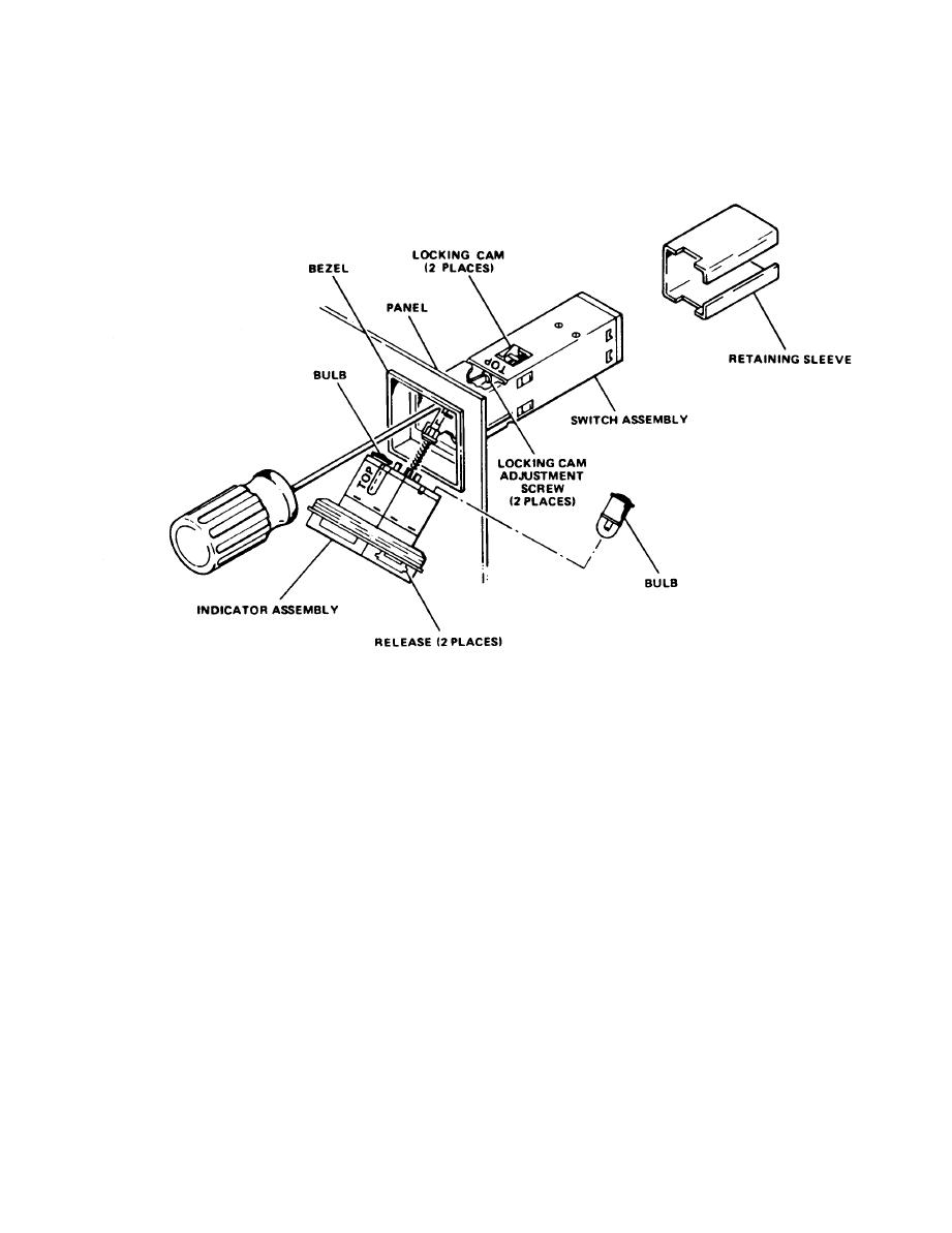
Figure 5-10. Switch/Indicator Replacement |
|
||
| ||||||||||
|
|
 TM 32-5865-218-24&P
Switch/Indicator Replacement
(4)
Slowly pull the switch/indicator forward until the wires
are exposed.
Tag the wires to identify terminal connections.
(5)
Unsolder wires from indicator/switch.
(6)
(7)
On the replacement switch/indicator, grasp the lens
assembly and pull forward about one inch.
(8)
Verify that the replacement switch/indicator contains two
lamps.
Use a screwdriver to turn the two locking cam adjustment
(9)
screws fully CCW.
(10) Solder the wires to the switch/indicator as tagged.
|
|
Privacy Statement - Press Release - Copyright Information. - Contact Us |
