 |
|||
|
|
|||
|
|
|||
| ||||||||||
|
|
 TM 32-5865-218-24&P
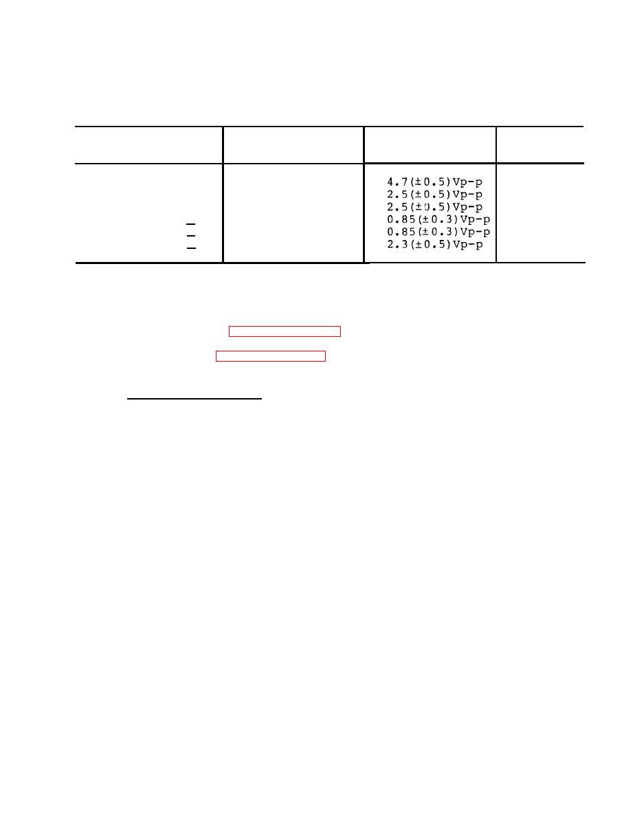
Countermeasures Control Audio Test Connections
and Display Data
Defective
Normal
Test oscillator
component
(+)
(+)
indication
(-)
(-)
T4
J2-C
J2-E
J6-C
J6-D
T9
J2-E
J6-q
J2-G
J6-p
T10
J6-b
J6-p
J6-q
J6-a
J6-S
T6
J6-k
J6-R
J6-j
T5
J2-E
J6-k
J2-P
J6-j
T7
J6-F
J6-E
J6-k
J6-j
This paragraph contains general main-
5-10. Maintenance Procedures.
tenance procedures that are common to the ECM panel indicator and the
For the ECM panel indicator, remove the
countermeasures control.
enclosure as given in paragraph 5-11a and perform the following
items. For the countermeasures control, remove the top and bottom
covers as given in paragraphs 5-12a and 5-12c, then perform the
following items.
a. Chassis Inspection. To inspect the ECM panel indicator or the
countermeasures control chassis mounted components, proceed as
follows:
Check for discolored, burned or cracked wire insulation,
(1)
or broken wires or terminals. Also check for damaged
heat shrink tubing.
(2)
Check cables for correct pin depths.
Check for loose or broken tie wrap mounts, mounting
(3)
clamps, or tiedown straps.
(4)
Check for cracked circuit breaker casings and for damaged
terminal boards.
(5)
Check for discolored (cold) , cracked, or loose solder
connections.
Check for leaking, bulging, or burned transformers,
(6)
capacitors, or filters.
Check for discolored, burned or cracked diodes, resistors
(7)
or other semiconductors devices.
Check for damaged brackets, covers, housing, and plates.
(8)
Check for loose or missing attaching hardware.
|
|
Privacy Statement - Press Release - Copyright Information. - Contact Us |