 |
|||
|
|
|||
|
Page Title:
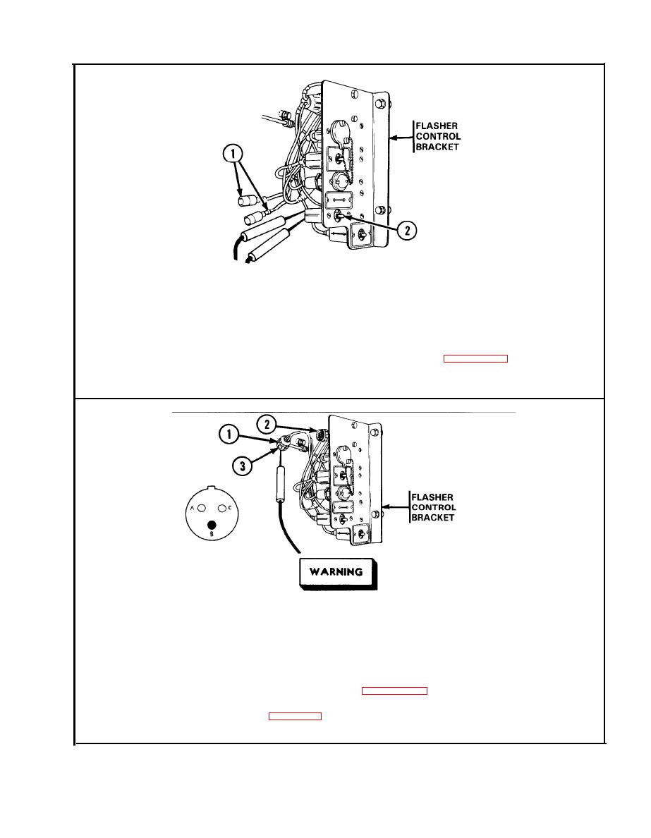
Cab Flasher Head light and Dome Light Circuit. (Cont) |
|
||
| ||||||||||
|
|
 TM
9-2350-238-20-2
(1)
Cab signal flasher headlight and flasher indicator lamps
are
not
operating
when
MASTER and FLASHER SIGNAL switches are ON.
Disconnect both leads 325 (1) from FLASHER SIGNAL switch (2). Connect
S t e p 1.
multimeter to FLASHER SIGNAL switch. Set FLASHER SIGNAL switch ON.
If multimeter indicates continuity, go to step 2. If multimeter indicates in-
finity, replace FLASHER SIGNAL switch,
refer
to
Set
FLASHER
SIGNAL switch OFF. Connect leads.
Make
sure
MASTER
switch
is
OFF
before
repairing
electrical
com-
ponents. Failure to observe this warning could result in injury to
personnel.
Disconnect
connector
(1)
from
flasher
assembly
(2).
Place
red
probe
in
Step 2.
socket B (3) (lead 325). Ground black probe. Set MASTER switch ON.
Set
FLASHER SIGNAL switch ON. If multimeter indicates about 24 volts,
replace flasher assembly, refer to page 2-271. If multimeter indicates no
voltage, repair lead 325 between flasher assembly and FLASHER SIGNAL
switch, refer to page 2-66. Set MASTER switch OFF. Set FLASHER
SIGNAL
switch
OFF.
Connect
connector.
|
|
Privacy Statement - Press Release - Copyright Information. - Contact Us |
