 |
|||
|
|
|||
|
|
|||
| ||||||||||
|
|
 TM 9-2350-238-20-1
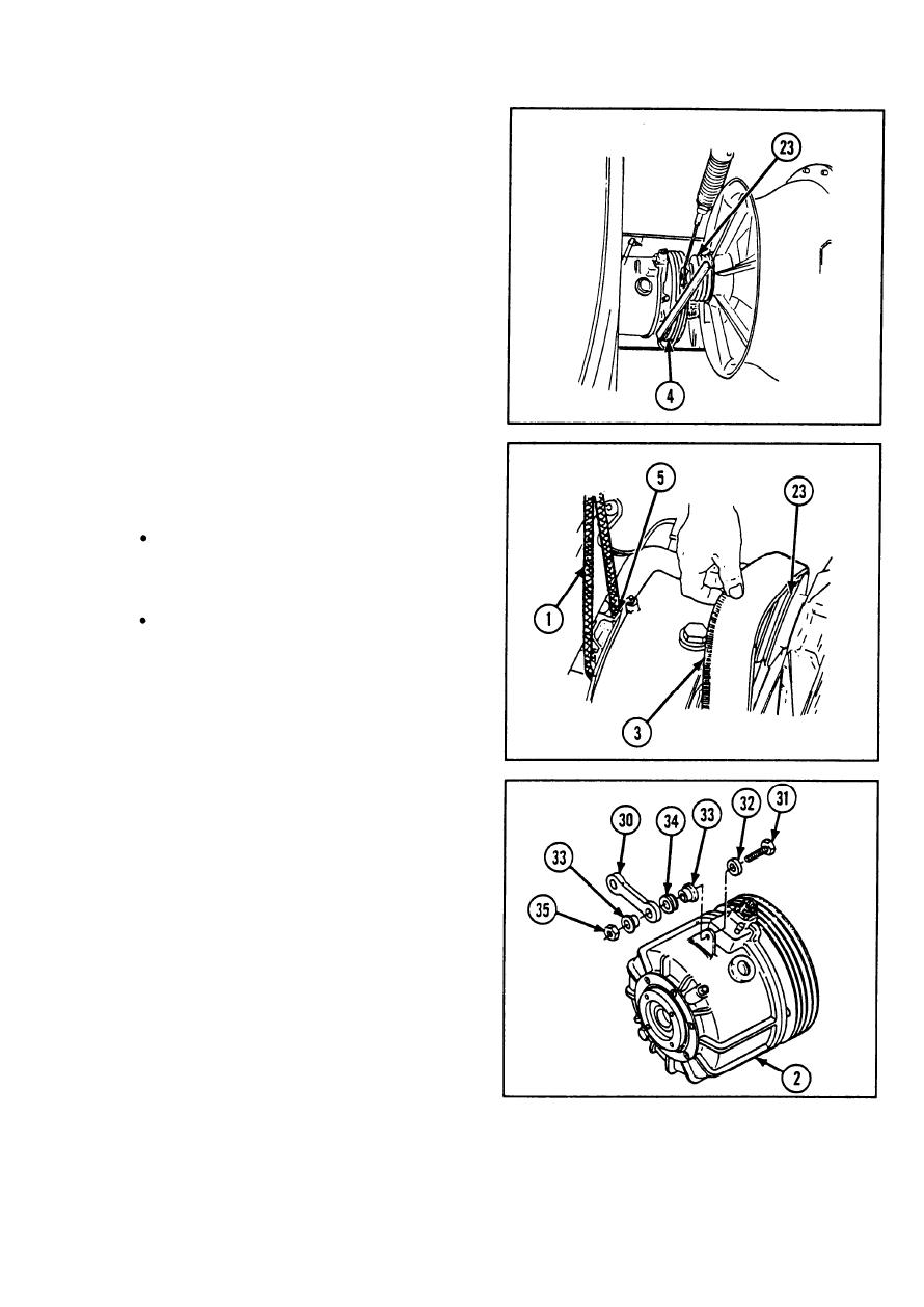
23
Place straightedge between outside face
of groove pulley (23) and outside face of
clutch groove pulley (4).
24
Tap groove pulley (23) lightly toward
radiator cooling vaneaxial fan with soft-
faced mallet.
25
Position groove pulley (23) about 1/16 in.
(1.59 mm) forward of clutch groove pulley
(4).
26
Tighten two socket head capscrews (25)
to 20 ft-lb (27 N-m) evenly in 5 ft-lb
(7 N-m) increments.
27
Recheck alignment of groove pulley (23)
and clutch groove pulley (4) with
straightedge.
NOTE
Faces of groove pulley and
clutch groove pulley should be
parallel and in same plane.
It may be necessary to loosen
two socket head capscrews in
groove pulley and readjust as in
steps 24 thru 27. Repeat as
required to achieve proper
alignment.
28
Place sling (1) under bearing unit drive
shaft (5).
29
Lift bearing unit drive shaft (5) enough to
slide V-belt (3) on groove pulley (23).
Install connecting link (30) to vehicular
30
drive (2), and secure with screw (31 ), flat
washer (32), two sleeve spacers (33),
nonmetallic grommet (34), and new self-
locking nut (35).
31
Remove sling (1).
2-551
|
|
Privacy Statement - Press Release - Copyright Information. - Contact Us |
