 |
|||
|
|
|||
|
Page Title:
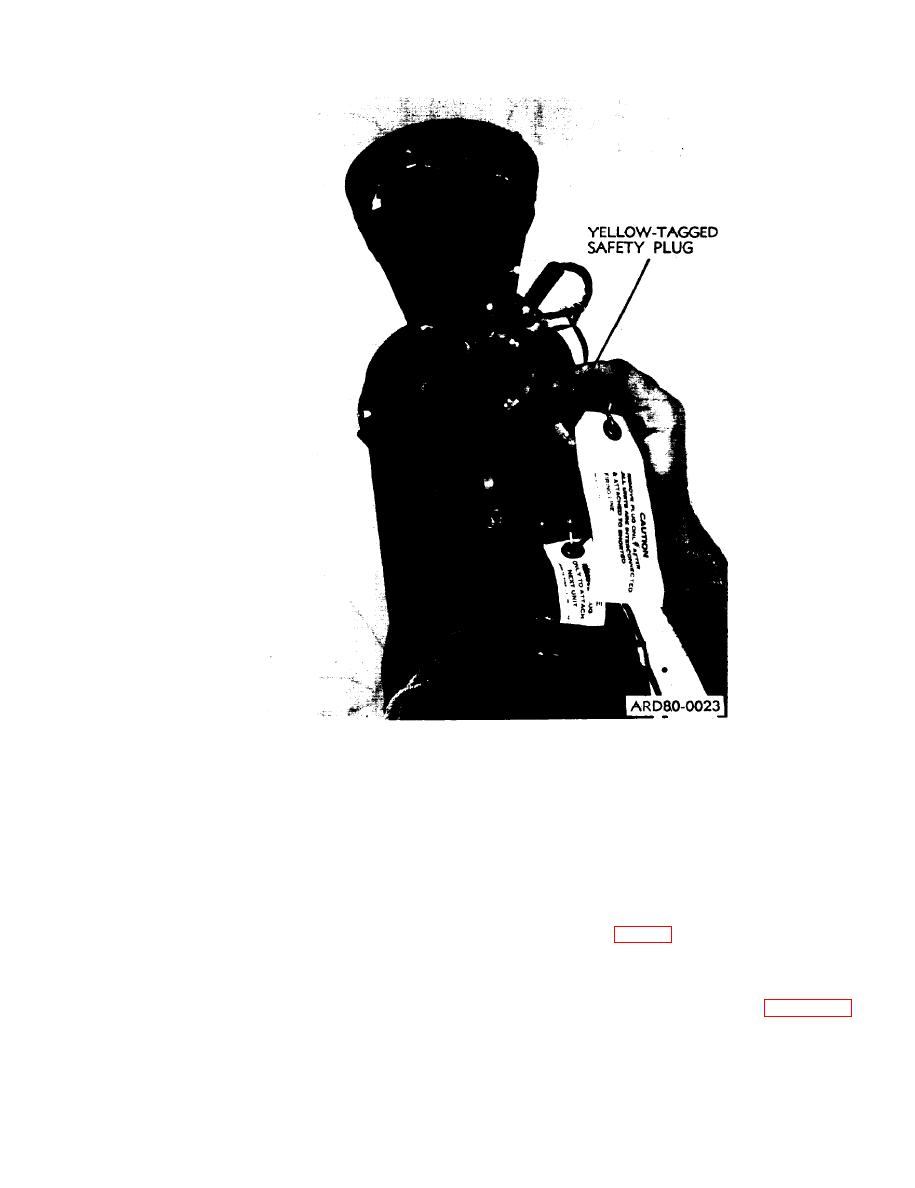
Figure 2-12. Removing yellow-tagged safety plug. |
|
||
| ||||||||||
|
|
 TM 9-1375-213-12-1
Figure 2-12. Removing yellow-tagged safety plug.
(1) Remove and retain continuity plugs (fig.
and the detonating cords are all on the same side.
Take care not to kink the detonating cord. Tape
2-15) from all kits EXCEPT farthest kit.
the junctions together and tape the detonating
(2) Assure that the continuity plug is threaded
cords adjacent to the junctions as well. Make sure
onto the interkit connector of the farthest kit in
everything remains properly connected and that
order to complete the circuit.
the tape is secured.
(3) Remove the firing lead plug from the firing
c. Interconnection of Rocket Motors.
cable connector of the farthest kit and thread the
cable connector (fig. 2-16) onto the inter-kit con-
NOTE
nector on next kit in line.
The suggested method of rocket motor in-
(4) Repeat interconnecting procedure of (3),
terconnection is to have operator begin
above, with each kit in line, working from farthest
with the kit farthest from the blasting
kit toward nearest kit, as shown in figure 212.
machine and work toward the kit nearest
the blasting machine. (The designations
(5) Do not remove the firing lead plug from
of "farthest kit" and "nearest kit," as used
the firing cable connector of the firing circuit of
hereafter, refer to the position of the kits
the nearest kit. Check to assure that plug is prop-
in relation to the blasting machine.)
erly secured to cable.
2-15
|
|
Privacy Statement - Press Release - Copyright Information. - Contact Us |
