 |
|||
|
|
|||
|
Page Title:
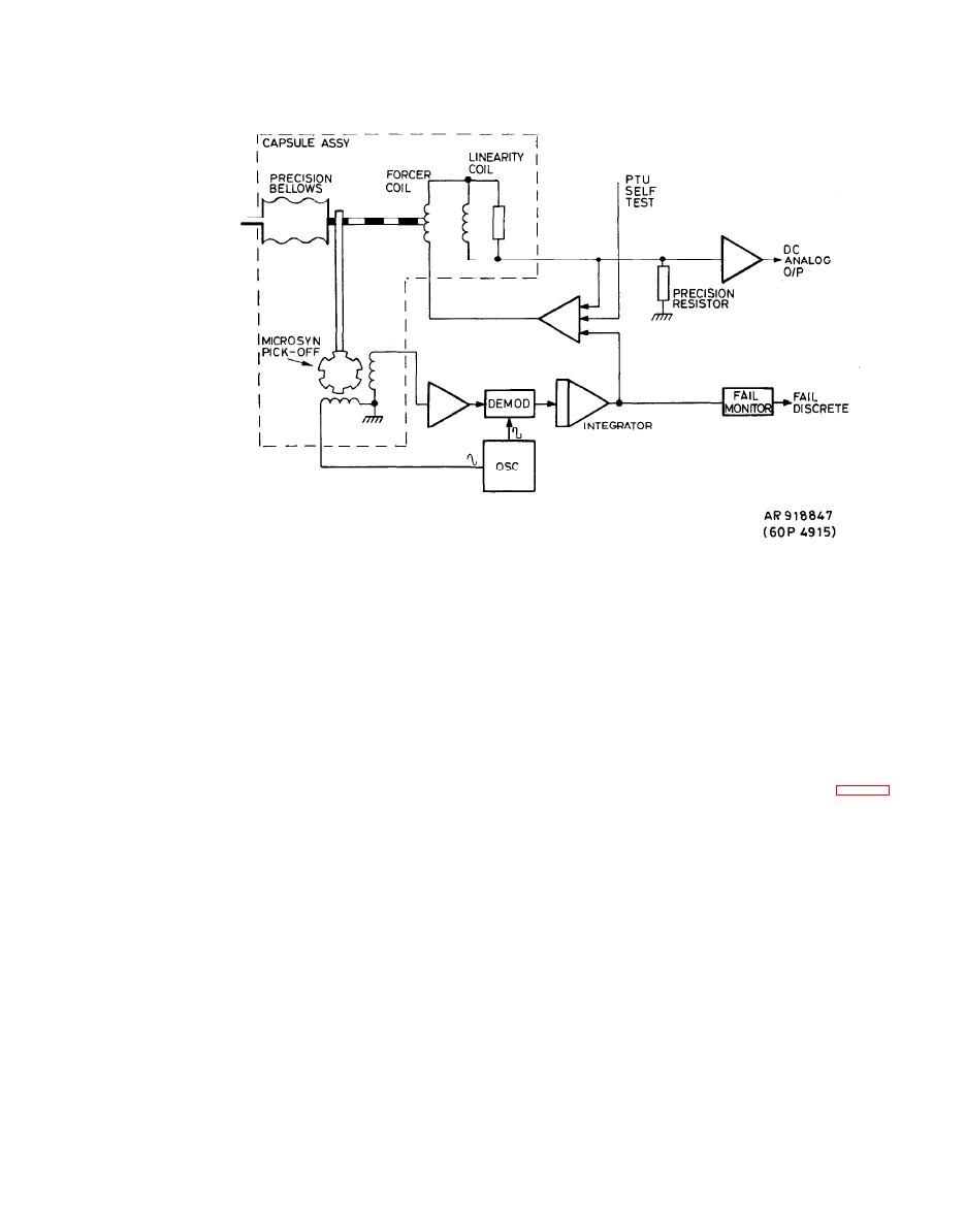
Figure 1-19. Transducer Control Block Diagram. |
|
||
| ||||||||||
|
|
 TM 9-1270-219-13&P
by the demodulator and the resulting error signal is integrated
(c) Temperature correction is effected digitally by
the CPU by reference to the temperature-sensing coil in the
and used to drive the power transistors. These supply the
transducer and the temperature characteristic which is
current
for
the
forcer
coil
to
correct
the
bellows
stored in a unique PROM mounted on the PTU circuit
attempted movement. A precision resistor is used to sense
board.
the
amount
of
current
required,
and
the
output
is
b u f f e r e d before being presented as a dc analog of the
pressure sensed by the bellows. The output buffer is also
b. Central Processor Unit (CPU). The CPU (fig. 1-20)
used to sum-in corrections for the transducer's nominal
is based on a 16-bit microprocessor which has separate
offset and gain.
address and data buses and can interface with standard
TTL and MOS components. The CPU also includes a 3K x
16 Programmable Read Only Memory (PROM), 256 x 16
(3) Temperature Correction. Both transducers exhibit
Random Access Memory (RAM), a clock generator, timer,
temperature sensitivity which causes repeatable
datum
D/A converter, input and output interface ports, and a
and gain shifts.
serial 64-bit buffer for interface to the FCC. Data is
transferred
between
the
memory
and
memory-mapped
i n p u t / o u p u t interfaces via a 16-bit data bus, and memory
addresses are decoded from a 15-bit address bus. The
(a) Datum shift occurs between the pick-off null
microprocessor runs at a 2MHz clock rate.
relative to the mechanical null, causing repeatable
non-linear characteristics in each transducer.
(1) M e m o r y . Program and fixed data constants are
stored
in
six
1024
x
8
PROMS.
Pressure
transducer
characterization constants are stored in two 32 x 8
P r o g r a m m a b l e Read Only Memories (PROMS) located on
(b) Gain shifts are a function of the permanent
the PTU and linked to the CPU by the 16-bit data bus and
magnetic field strength and are repeatable for each
five lines of the address bus.
transducer.
|
|
Privacy Statement - Press Release - Copyright Information. - Contact Us |
