 |
|||
|
|
|||
|
|
|||
| ||||||||||
|
|
 TM 9-1270-212-14&P
(7) Using the serrated cuts in the supports (forward
NOTE
and aft), move the rails to align the borescope reticle with
Take care not to bump the bubble level
the gunner's target.
assembly after it has been adjusted on the TSU
( 8 ) Adjust the position of each support as
boresight device.
follows: Making certain that the serrations in the key
washer are aligned with the serrations in the support,
(2) Attach the LOD to the forward end of the
tighten the nut on the end of the mounting-bracket stud
gunner's rails so that the LOD bubble is forward.
until it is snug. Compress the quick-release plunger (12,
(3) Tighten the T-locks on the LOD T-bars until the
tighten the nut on the stud until the spring tension of the
LOD is firmly attached to the rails.
plunger will not return the support to its original position.
Then loosen the nut enough to have proper operation of
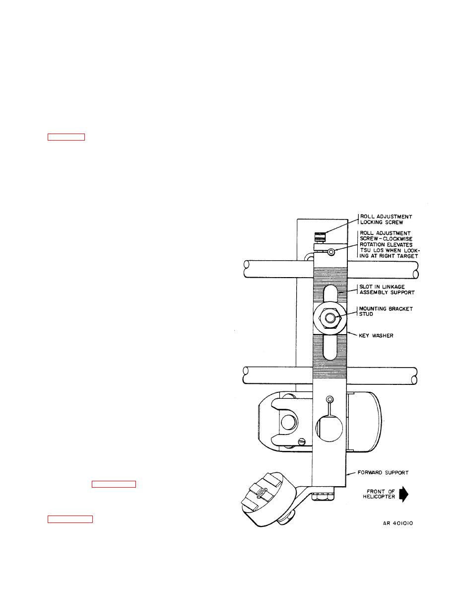
(4) Loosen the roll adjustment locking screw (fig.
the spring plunger.
4-5) and adjust the roll adjustment screw in the support
until the LOD bubble is again centered. Tighten the roll
(9) With the borescope in the LOD, recheck the
adjustment locking screw and recheck the bubble.
azimuth alignment. Remove the borescope.
b. XM128 Pilot's Rail Alignment. Transfer the LOD to
the forwardmost end of the pilot's rails. Insure that the
LOD bubble is at the forward end. Repeat steps a(4)
through (9) above for pilot's rail azimuth adjustment.
c. XM136 Pilot's Rail Alignment.
(1) Remove the LOD from the gunner's rails. Loosen
the LOD azimuth locking knob. Remove the alignment pin
from the rail clamp base, and rotate the rail clamp base
(approximately 180 degrees) until the 5.5 line on the rail
clamp base is aligned with the notch in the swivel plate.
Insert the alignment pin through the hole in the rail clamp
base, making sure that the alignment pin is firmly seated in
its hole in the swivel plate. Firmly tighten the azimuth
locking knob.
(2) Attach the LOD to the forwardmost end of the
pilot's rails. Insure that the LOD bubble is at the forward
end.
(3) Perform steps a(4) through (9).
a. Gunner's Rail Alignment.
NOTE
Step (1) below may be omitted if the LOD
bubble has not been disturbed since it was
locked in paragraph 4-5a(2) and if the LOD is
locked in the 0-degree position.
(1) With the LOD locked in the 0-degree position
forward, place the LOD on the TSU boresight device and
center the bubble. Lock the bubble in place.
|
|
Privacy Statement - Press Release - Copyright Information. - Contact Us |
