 |
|||
|
|
|||
|
Page Title:
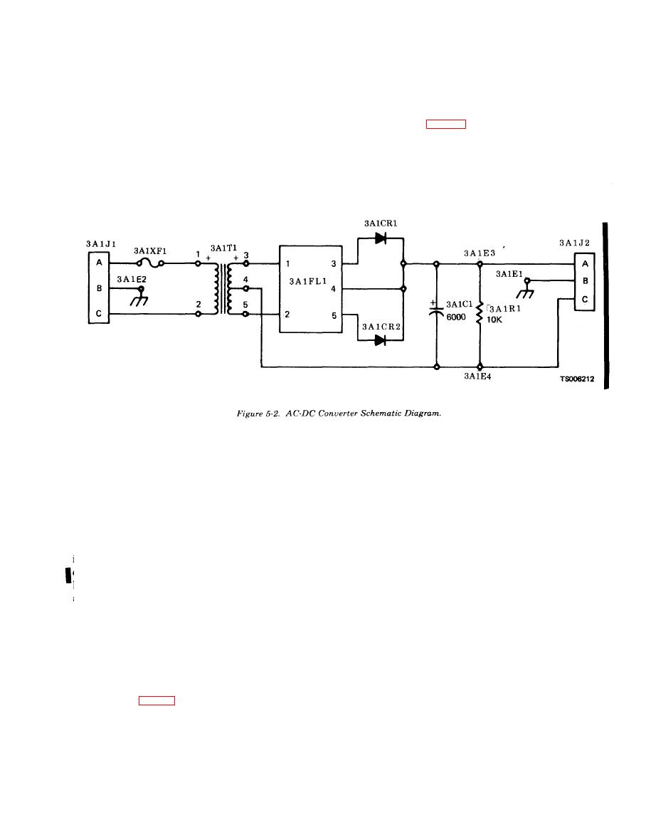
Figure 5-2. AC-DC Converter Schematic Diagram |
|
||
| ||||||||||
|
|
 TM 5-6675-250-34
(2) Inspect connectors for bent pins and
b. Cleaning.
e v i d e n c e of burns.
(1) Use low pressure, 5 to 10 psi, compressed air
( 3 ) Test output voltage.
t o clean the converter interior.
(a) Connect a 20-ohm 100 watt load resistor
(2) Wipe the case with a lint free cloth moistened
across the converter DC OUTPUT receptacle 3A1J2,
with trichloroethane, Federal Specification, O-T-
pins A and C. (fig. 5-2).
2 3 6 , or equivalent solvent.
c. I n s p e c t i o n .
(1) Visually inspect the components for evidence
o f burns and arcing.
(3) Position new component in place and secure
(b) T h r o u g h
the
AC
INPUT
receptacle,
w i t h attaching parts.
c o n n e c t t h e c o n v e r t e r- to a 115 Vac, 60-400 Hz
( 4 ) Solder electrical leads to component in ac-
p o w e r source.
c o r d a n c e with identifying tags.
(c) U s i n g a m u l t i r n e t e r , c h e c k t h e o u t p u t
b. Resistor.
v o l t a g e at the DC OUTPUT receptacle.
(1) U n s o l d e r e l e c t r i c a l l e a d s f r o m d e f e c t i v e
(d) Verify that the output voltage is 26 to 30
r e s i s t o r and tag for identification.
Vdc.
( 2 ) Position new resistor in place and solder
(e) Verify that the output ripple is 0.25 to
electrical leads in accordance with identifying tags.
0.40 Vrms.
c. D i o d e s .
( 4 ) Test voltage regulation of loads by check-
ing the converter output across pins A and C of re-
( 2 ) Remove nut and washer securing diode to
ceptacle 3A1J2 with no load, a 40-ohm, 50 watt,
bracket.
load, and a 10-ohm, 100 watt, load. Verify the volt-
( 3 ) Position new diode in place. The insulated
age output is as follows:
washers must be in place to insure that the diode is
output (10%)
Input
Load
p r o p e r l y insulated. Secure with nut and washers.
33.5 Vdc
115 Vac,
60 Hz
No load
( 4 ) Solder electrical lead to terminal of diode.
32.5 Vdc
115 Vac,
400 Hz
No load
d. Filter.
29.7 Vdc
115 Vac,
60 Hz
40 ohm
(1) Unsolder electrical leads from defective filter
28.9 Vdc
115 Vac,
400 Hz
40 ohm
24.1 Vdc
115 Vac,
60 Hz
10 ohm
a n d tag for identification.
23.2 Vdc
115 Vac,
400 Hz
10 ohm
( 2 ) Remove attaching parts securing filter to
h o u s i n g and converter (two places).
5-3. Repair (fig. 5-1)
(3) Position new filter in place and secure with
a. Transformer and Capacitor.
attaching parts.
(1) Unsolder electrical leads and tag for iden-
(4) Solder electrical leads to filter.
tification.
5-4. Reassembly
(2) Remove attaching parts securing component
Position the cover onto the housing and secure with
t o converter (four places).
six screws.
Change 1, 5-3
|
|
Privacy Statement - Press Release - Copyright Information. - Contact Us |
