 |
|||
|
|
|||
|
Page Title:
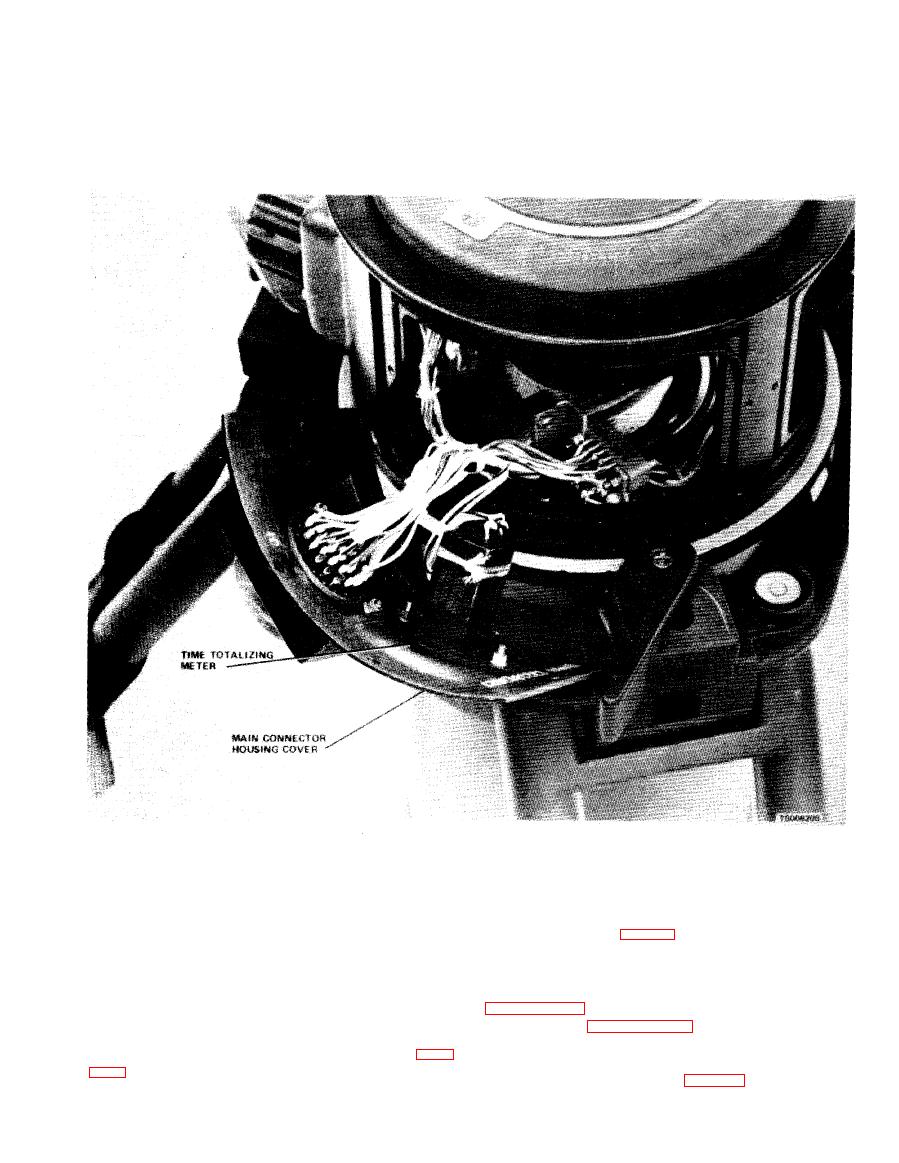
Figure 4-7. Time totalizing meter removal and installation. |
|
||
| ||||||||||
|
|
 TM 5-6675-250-34
(2) Unsolder and remove the wires from the
screws securing the time totalizing meter to the
t i m e totalizing meter.
housing
cover.
(3) Cut the lacing cord holding the lead wires to
(5) Remove the time totalizing meter and
t h e body of the meter.
g a s k e t from the cover.
( 4 ) Remove the two self locking nuts and two
(5) Mount the housing cover to the housing
b . Installation.
u s i n g the ten attachment screws.
(1) Mount the replacement time totalizing
m e t e r to the main connector housing cover, using
two nuts and two screws. Make sure that the rubber
a. R e m o v a l .
gasket is in place between the cover and the meter.
(1) Remove the caging mechanism cover and
( 2 ) Connect and solder meter wires. The wire
outer shield by following the instructions in
m a y be reversed from the original configuration as
t h e r e is no polarity involved.
i n s t r u m e n t per paragraph 4-6b, steps (1) and (2).
(3) Lace the lead wires to the body of the meter.
( 2 ) Engage the caging clutch by inserting an
( 4 ) Prepare ten cover attachment screws (para
orangewood stick, or similar tool, between the upper
h o u s i n g and the clutch, half (fig. 4-8).
4-11
|
|
Privacy Statement - Press Release - Copyright Information. - Contact Us |
