 |
|||
|
|
|||
|
Page Title:
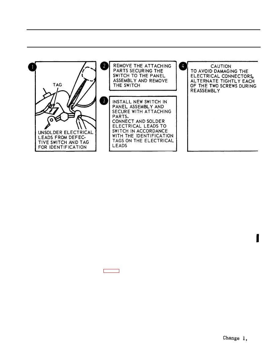
Figure 2-77. Removal of MODE and TEST SELECT switch. |
|
||
| ||||||||||
|
|
 TM 5-6675-250-34
Table 2-1. Troubleshooting - Continued
MALFUNCTION
TEST OR INSPECTION
CORRECTIVE
ACTION
TS 006316
(8). Unsolder the electrical leads from the defective switch and tag for identification.
(9). Install new switch in panel assembly and secure with attaching parts. Connect and solder electrical
leads to switch in accordance with the identification tags on the electrical leads.
CAUTION
To avoid damaging the electrical connectors, alternate tightening each of the two screws during reassembly.
(10). Install printed circuit board, but do not tighten mounting screws. Connect the two electrical
connectors and secure by tightening two screws. Fasten ten screws that secure printed circuit
board to mounting brackets.
(11). Place edge-lighted panel over connector, seat properly and secure with five mounting screws.
(12). Install BIAS control locking knob and BIAS knob on switch shaft. Secure BIAS knob by
tightening setscrews.
(13). Install TEST SELECT switch knob on shaft with pointer at source voltage position. Install
MODE SELECT switch knob on shaft with pointer at GC position. Secure each knob by
tightening setscrews.
(14). Install electronic control panel assembly in case and secure with eight captive screws.
14. CAGING INOPERATIVE
Step 1. Check to see if caging link is out of adjustment.
a. Remove eight screws attaching the outer shield to the upper housing assembly and remove.
b. To keep foreign particles from entering. the inner parts of the instrument, place masking tape between the housing
and the inner shield, except in the area of the caging link.
c. Set the instrument on the work surfaces, resting on the inner shield and in the upright position. Be careful
not to damage the shield as the shield material is very soft and sensitive to shock.
d. Loosen the caging link jam nut (fig. 2-78). Install the cage-uncage knob temporarily, so that the
caging mechanism may be actuated.
2-63
|
|
Privacy Statement - Press Release - Copyright Information. - Contact Us |
