 |
|||
|
|
|||
|
Page Title:
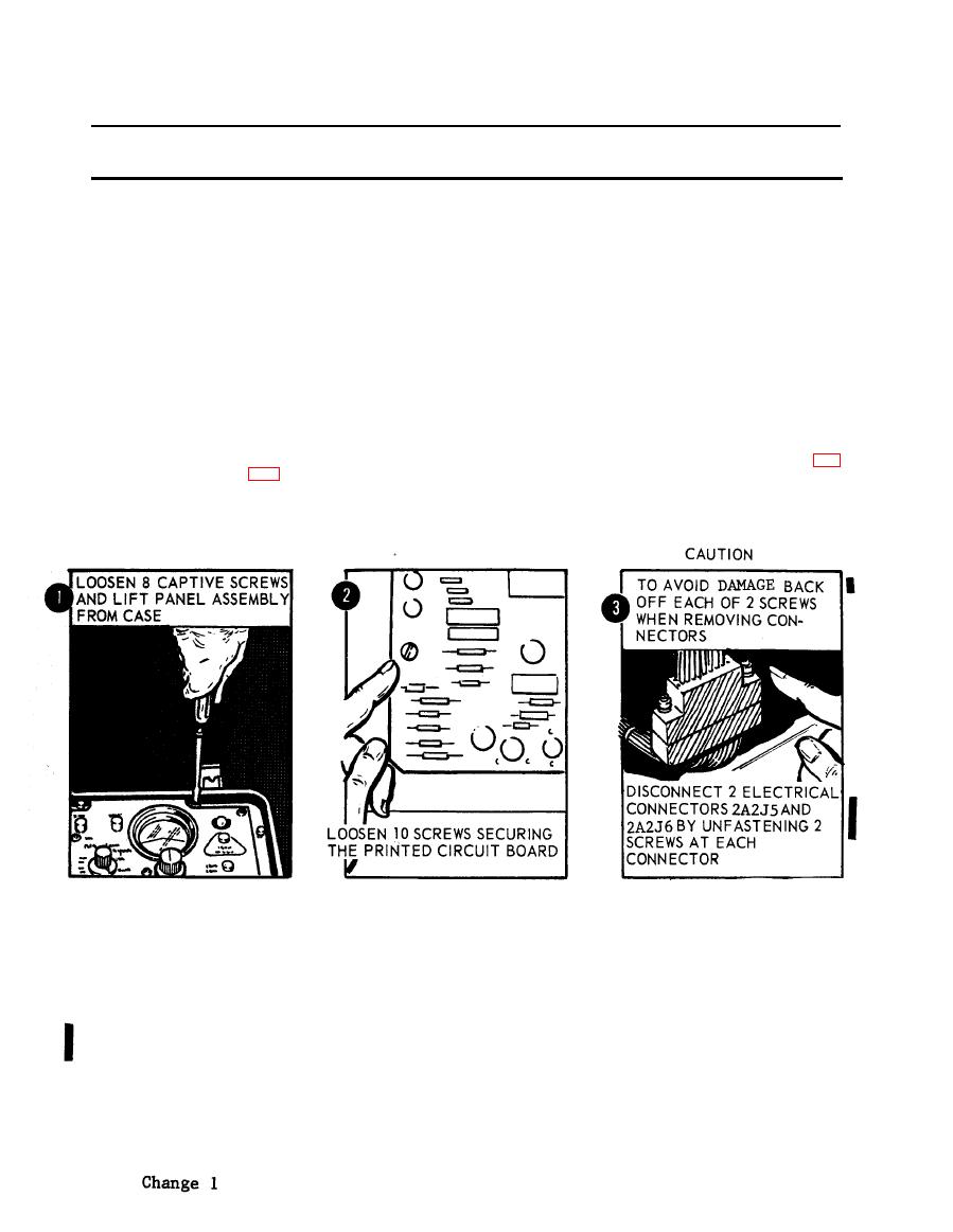
Figure 2-40. Removal of ECU panel assembly. |
|
||
| ||||||||||
|
|
 TM 5-6675-250-34
Table 2-1. Troubleshooting - Continued
MALFUNCTION
TEST OR INSPECTION
CORRECTIVE ACTION
CAUTION
To avoid damaging the electrical connectors, alternate tightening each of the two screws during reassembly.
(10). Install printed circuit board, but do not tighten mounting screws. Connect the two electrical
connectors and secure by tightening two screws. Fasten ten screws that secure printed circuit
board to mounting brackets.
(11). Place edge-lighted panel over connector, seat properly and secure with five mounting screws.
(12). Install BIAS control locking knob and BIAS knob on switch shaft. Secure BIAS knob by
tightening setscrews.
(13). Install TEST SELECT switch knob on shaft with pointer at source voltage position. Install
MODE SELECT switch knob on shaft with pointer at GC position. Secure each knob by
tightening setscrews.
(14). Install electronic control panel assembly in case and secure with light captive screws.
Step 5. Check for a defective test meter.
a. Depress PRESS to test SWITCH.
b. If meter fails to provide required indication, meter is bad.
Replace a bad test meter.
(1). Loosen the eight captive screws and lift the electronic control panel assembly from the case (fig.
TS 006279
(2). Unfasten ten screws securing the printed circuit board to the mounting brackets and loosen the
board to obtain access to electrical connectors.
CAUTION
To avoid damage to the electrical connectors, alternately back-off each of the two attaching screws when removing the
connectors.
(3). Disconnect two electrical connectors (2A2J5 and 2A2J6) by unfastening two screws at each
connector.
(4). Unsolder the electrical leads and tag for identification.
(5). Remove three nuts and screws attaching tbe meter and remove from the electronic control panel
assembly.
(6). Install a new meter in tbe electronic control panel and secure with three nuts and screws.
(7). Connect and solder the electrical leads to the switch in accordance with the identification tags on
the leads.
2-32,
|
|
Privacy Statement - Press Release - Copyright Information. - Contact Us |
