 |
|||
|
|
|||
|
Page Title:
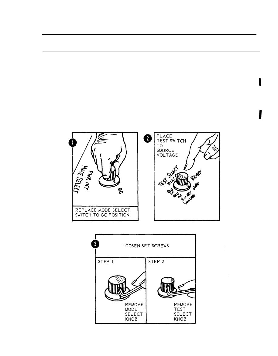
Figure 2-22. Removal of MODE and TEST SELECT switch knobs. |
|
||
| ||||||||||
|
|
 TM 5-6675-250-34
Table 2-1. Troubleshooting-Continued
MALFUNCITON
TEST OR INSPECTION
CORRECTIVE ACTION
b. Unfasten ten screws securing the printed circuit board to mounting brackets and loosen the board to obtain access
to electrical connectors.
CAUTION
To avoid damage to the electrical connectors, alternately back-off each of the two attaching screws when removing the
connectors.
c. Disconnect two electrical connectors (2A2J5, 2A2J6) by unfastening two screws at each connector.
d. Check continuity between the input pins of the mode select switch and the position pins. Check voltage drop between
pin 2 of the theodolite bright control and pins 1 and 3 while rotating the control shaft.
If continuity is not present when checking the MODE SELECT switch and voltage drop exist when checking
theodolite bright control, replace them.
(1). Place MODE SELECT switch to GC position.
(2). Place TEST SELECT switch to SOURCE VOLTAGE positions.
(3). Loosen MODE SELECT and TEST SELECT knob setscrews with 5/64 and 0.050-inch hex
wrench, respectively, and remove knpb from switch shaft.
TS 006261
Change 1,
|
|
Privacy Statement - Press Release - Copyright Information. - Contact Us |
