 |
|||
|
|
|||
|
Page Title:
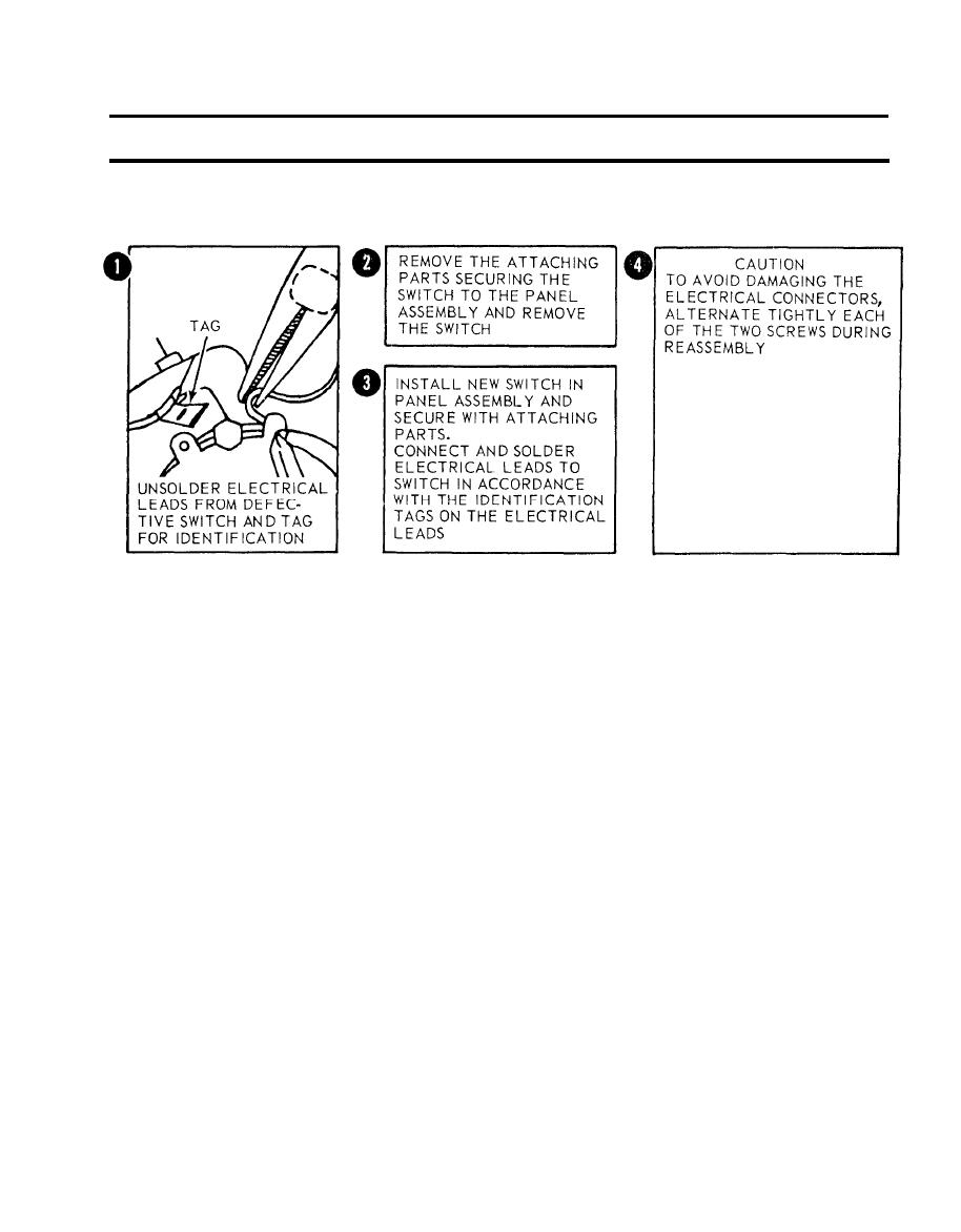
Figure 2-19. Removal of MODE SELECT switch. |
|
||
| ||||||||||
|
|
 TM 5-6675-250-34
Table 2-1. Troubleshooting - Continued
MALFUNCTION
TEST OR INSPECTION
CORRECTIVE ACTION
TS 006258
electrical leads to switch in accordance with the identification tags on the electrical leads.
CAUTION
TO avoid damaging the electrical connectors, alternate tightening each of the two screws during reassembly.
m.
Install printed circuit board, but do not tighten mounting screws. Connect the two electrical
connectors and secure by tightening two screws. Fasten ten screws that secure printed circuit
board to mounting brackets.
n
Place edge-lighted panel over connector, seat properly and secure with five mounting screws.
o.
Install BIAS control locking and BIAS knob on switch shaft. Secure BIAS knob by tightening
setscrews.
p.
Install TEST SELECT knob on shaft with pointer at source voltage position. Install MODE
SELECT knob on shaft with pointer at GC position. Secure each knob by tightening set-
screws.
Install electronic control panel assembly in case and secure with light captive screws.
q.
3. THEODOLITE LIGHT CIRCUIT INOPERATIVE WHEN MODE SELECT SWITCH IS IN THEO ILLUM POSITION AND
THEO BRT CONTROL IS FULLY CW.
Step 1. Check for defective theodolite lamp.
a. Ensure that the power is off.
b. Rotate the protective cap counterclockwise and remove.
c. Remove the lamp from the socket.
d. Visually inspect lamp for a burned out filament.
(1). Place a good lamp in the socket.
(2). Position the protective cap over the socket and turn clockwise until finger tight
Step 2. Check for a bad interconnect cable.
a. Disconnect the interconnect cable from the receptacle on the ECU and GRU.
2-15
|
|
Privacy Statement - Press Release - Copyright Information. - Contact Us |
