 |
|||
|
|
|||
|
Page Title:
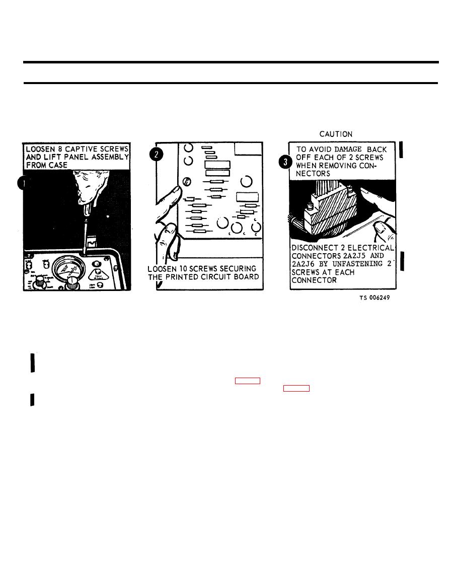
Figure 2-10. Removal of ECU panel assembly. |
|
||
| ||||||||||
|
|
 TM 5-6675-250-34
Table 2-1. TroubleshootingContinued
MALFUNCTION
TEST OR INSPECTION
CORRECTIVE ACTION
b. Unfasten ten screws eecuring the printed circuit board to mounting brackets and loosen the board to
obtain access to electrical connectors.
CAUTION
To avoid damage to the electrical connectors, alternately back-off each of the two attaching screws when removing the
connectors.
c. Disconnect two electrical connectors (2A2J5 and 2A3J6) by unfastening two screws at each connector.
(1). Place MODE SELECT switch to GC position (fig. 2-11).
(2). Place TEST SELECT switch to SOURCE VOLTAGE position (fig. 2-11).
(3). Loosen MODE SELECT and TEST SELECT knob setscrews with 5/64 inch and 0.050-inch
hex wrench, respectively, and remove knob from switch shaft.
2-8, Change 1
|
|
Privacy Statement - Press Release - Copyright Information. - Contact Us |
