 |
|||
|
|
|||
|
Page Title:
CHAPTER 2 OPERATING INSTRUCTIONS |
|
||
| ||||||||||
|
|
 TM5-6350-264-14&P-6
NAVELEX EE181-AA-OMI-07A/E121 DT-545
TO 31S9-2FSS9-1-6
CHAPTER 2
OPERATING INSTRUCTIONS
Section I. OPERATING PROCEDURES
installed, tested, and connected to the J-SIIDS Control
2-1. CONTROLS AND INDICATORS. There are no
Unit.
operator controls or indicators on the GWS.
2-3. EMERGENCY OPERATION.
Operation with
2-2. NORMAL OPERATING PROCEDURES.
The
incomplete surveillance coverage or faulty tamper circuit
GWS is operationally ready after it has
been
should be held to a minimum.
Section II. THEORY OF OPERATION
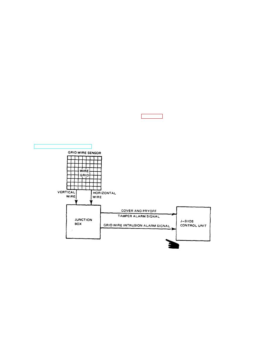
2-4. FUCTIONAL DESCRIPTION. The GWS provides
in the wire grid occurs or when one of the tamper
an intrusion alarm signal output when a break occurs in
switches is activated, the normally low resistance
the wire grid. A tamper alarm is activated when the
present across the output terminals changes to a high
cover is lifted or the chassis is pulled away from its
resistance(100, 000 ohms or more).
This high
mounting surface. These two signals are normally wired
resistance output to the J-SIIDS Control Unit activates an
in series into the sensor tamper input in the Control Unit,
alarm.
refer
to
TM5-6350-264-14&P-10.
Refer
to
Figure 2-1. Grid Wire Sensor Simplified Block Diagram 2-1
2-1
|
|
Privacy Statement - Press Release - Copyright Information. - Contact Us |