 |
|||
|
|
|||
|
|
|||
| ||||||||||
|
|
 (10) Disconnect
the three secondary
2-13. Load Break Switch Removal
conductors at the switch connections. Identify and tag
WARNING
each conductor for easier installation of switch.
All power must he removed so that substation
(11) Across the bottom front of the switch is a
is completely de-energized before attempting
narrow insulating barrier strip (fig. 2-21. Loosen and
to remove load break switch.
Serious
remove the two screws 12, one for each end) that fasten
personnel injury and/ or damage to equipment
the barrier to the cabinet mounts.
may result.
b.
To Remote Load Break Switch.
a.
Disconnect Load Break Switch.
(1) The switch is mounted to the cabinet
(I)
Clear trailer deck of all unnecessary
mounting rails by five vertical bolts, nuts and washers,
equipment.
three on the left side and two on the right. The right front
(2) Check and make sure all primary power
bolt has a spacer also.
has been removed to unit if switch is being replaced in a
(2) Loosen and remove the five bolts, nuts
field installation.
and washers (the vertical ones mounting the switch frame
(3) Loosen and remove the four hex head
to the cabinet rails).
bolts and washers from the upper front hinged panel.
(3) Lift and remove switch care must be
(4) loosen and remove the three hex head
taken not to hit and break the insulating barriers when
bolts and washers from the lower front hinged panel.
removing switch and when setting it down after removal.
(5) On the rear loosen and remove the six
(4) Replace the two, barriers and their
hex head bolts, lockwashers and plain washers securing
hardware are that were removed in preceding step a(8)
each panel, upper and lower. Remove upper and lower
panels.
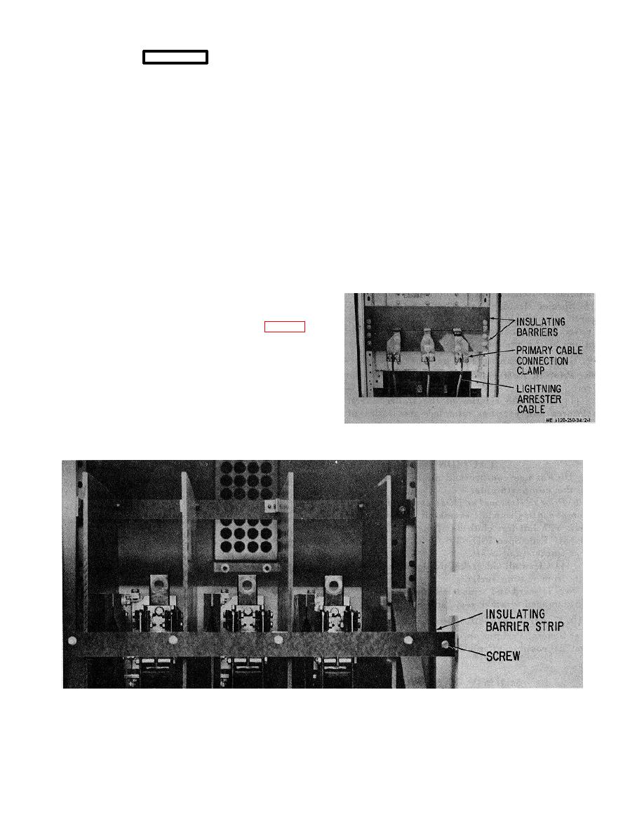
(6) If switch is being removed in a field
installation, disconnect the three primary conductors from
the connection clamps in the rear compartment (fig. 2-1).
(7) Disconnect the three leads from each of
the lightning arresters connected to the primary
connection clamp of switch.
(8) Loosen and remove the bolts, nuts and
washers securing the two horizontal insulating barriers
around the primary connection bar.
(9) In front swing open the upper and lower
hinged panels.
Figure 2-1. High voltage cabinet, rear upper and lower
panels removed.
Figure 2-2. High voltage cabinet, upper front panel open.
2-4
|
|
Privacy Statement - Press Release - Copyright Information. - Contact Us |
