 |
|||
|
|
|||
|
Page Title:
Figure 6-6. Installing first stave |
|
||
| ||||||||||
|
|
 TM 5-5430-209-12
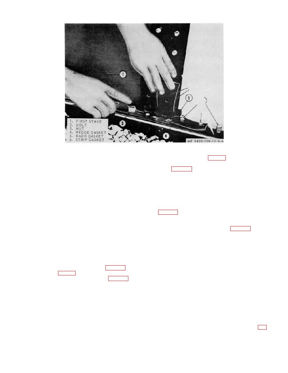
Figure 6-6. Installing first stave.
(4) Install nuts (3, fig. 6-6) loosely on all chime
(2) Install nuts (3) on chime bolts (2) to hold
bolts (2), except two right ones, of the first intermediate
stave in position. Run down nuts by hand to fasten
stave (1, fig. 3-12).
stave loosely. Do no install nuts on two end bolts at
NOTE
each side of stave.
As remaining staves are installed, check
carefully the position of all radii, wedge, and
NOTE
strip gaskets.
Nuts are not tightened until the last stave in ring
is in place.
CAUTION
d. Remaining Intermediate Staves.
Radii gaskets must be placed between
(1) Face the outside of first intermediate stave
chimes and rubber gasket material at top
(1, fig. 3-12) and install the next 17 staves to the right
and bottom seams of all staves to insure a
of this stave (1), or in a counterclockwise direction
leakproof connection.
around the bottom. Follow the procedure in c above.
(2) Assemble hook ladder (1, fig. 3-13) and
hook it over the inside of the staves.
(3) Two special gaskets are required. Wedge
(3) As staves are installed, stand on ladder and
gasket (4) fills the space by the lap offset at vertical
hammer heads of all bolts (2) squarely into the
seam. Radii gasket (5) is installed underneath strip
channels. Install bolts in the alining holes and seat the
gasket (6) at bottom and top chimes of the stave.
bolts.
c. First Intermediate Stave.
CAUTION
(1) Set first intermediate stave (1, fig. 3-12)
All bolt heads must be seated squarely in
over chime bolts (2, fig. 6-6) so that its left seam will be
the stave joint channels to insure proper
outside the right seam on the first stave (2, fig. 3-12).
tightening of nuts.
(2) Use drift pins (3) in open bolt holes to aline
the holes in the first intermediate staves (1) with bolts in
(4) Move hook ladder to outside of tank.
the first stave (2). Install nuts (4) loosely on every sixth
Remove loose nuts and place a steel recessed washer,
or tenth bolt in each row to hold first intermediate stave
cupped side down, over each lap seam bolt. Install a
(1) in place.
nut loosely on each bolt.
(3) Install wedge gasket and radii gasket at
chimes on right seam of stave as instructed in b (3)
e. Last Stave.
above.
(1) To assist in installation of last stave (1, fig.
6-7), push all chime bolts (2) of the bottom flush with
gasket (3) to provide clearance for sliding in the last
stave.
6-6
|
|
Privacy Statement - Press Release - Copyright Information. - Contact Us |
