 |
|||
|
|
|||
|
Page Title:
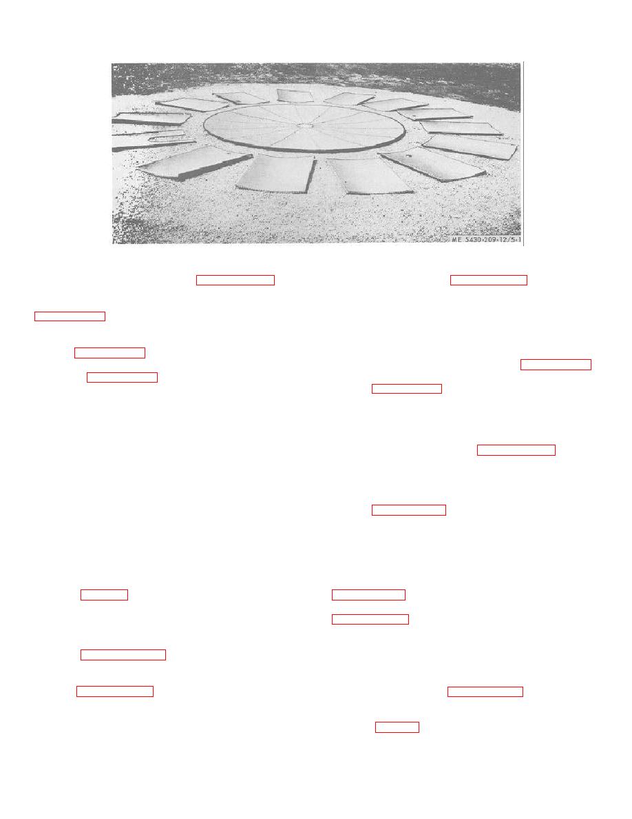
Figure 5-1. Layout of staves around tank bottom |
|
||
| ||||||||||
|
|
 TM 5-5430-209-12
Figure 5-1. Layout of staves around tank bottom.
radial seam. In paragraph 3-7 c (3),
eleven
intermediate
staves
are
and dress the staves.
d. Preparing Outer Edge of Tank Bottom. Refer to
installed.
5-10. Scaffold
Before installing the tank deck it is necessary to install a
tank bottom.
5-9. Installation of Side Staves.
portion of the scaffold components, provided in the
Refer to paragraph 3-7c and install the side staves.
storage tank erection outfit, around the top chime of the
NOTE
staves. Follow the procedure outlined in paragraph 3-8.
5-11. Dressing Top Chime
In paragraph 3-7 c (1), the first stave
Refer to paragraph 3-9 and dress the top chime.
and all subsequent staves straddle a
Section III. ASSEMBLY AND INSTALLATION OF CENTER SUPPORT LADDER
5-12. Assembly of Ladder
b. Assembling Ladder. Assembly procedures are
a. General. The ladder consists of a bolted, steel
identical to those described in paragraph 4-12. In step
(3), the assembled section contains 5 steps. In step (7),
angle section. Top of the ladder is fitted with a manhole
the short leg measures 9 feet, 5-5/16 inches from top
dome. Bottom of the ladder is fitted with ladder braces
flange of dome.
(flanged, flat, steel plates). Small ends of the deck
5-13. Installation of Ladder
plates are bolted to the manhole dome bottom flange.
Refer to paragraph 4-13 and install the ladder.
Section IV. ASSEMBLY AND INSTALLATION OF TANK DECK
5-14. General
5-17. Installation of Deck Plates
a. Layout of Assembled Plates.
The assembled deck consists of 14 tapered, flat, steel
Refer to
plates (1, fig. 3-20). There are three special plates: two
b. Adjustment of Center Support Ladder. Refer to
are fitted with a pressure vacuum valve, and the third is
fitted with a liquid level indicator. All plates are
interchangeable.
distance from top of tank bottom to outer face of top
5-15. Layout and Assembly of Plates
flange of dome is 9 feet, 6-9/64 inches.
c. Gin Pole. To install deck plates, remove and
Refer to paragraph 4-15, layout and assemble the
plates.
assemble the gin pole components, less foot spike,
5-16. Assembly of Special Plates
provided in the tank tool erection set.
Follow
procedures prescribed in paragraph 3-16 c.
Refer to paragraph 4-16 and assemble the three special
d. Installing First Deck Plate. The first plate
plates.
installed is one of two plates with a pressure vacuum
valve (2, fig. 3-20. The other plate with a
5-2
|
|
Privacy Statement - Press Release - Copyright Information. - Contact Us |
