 |
|||
|
|
|||
|
|
|||
| ||||||||||
|
|
 TM 5-5430-209-12
(2) Determine which end of the rails (1 and 2)
will be the bottom. Install steps (4) from bottom toward
top of the ladder.
(3) Four steps (4) make up the assembled
section. Insert bolts (3) through ends of step (4) and
rails (1 and 2) in that order. Install nut (5) on each bolt
(3) protruding through the rails. Tighten bolts after all
steps are installed.
(4) Face the 28-bolthole flange of the
manhole dome (7) and slide it over the top of the rails.
Use a drift pin (3, fig. 3-12) and aline three boltholes at
top of rails with similar holes in side of dome. Insert
bolts (6, fig. 4-7) through rails (1 and 2) and dome (7) in
that order. Apply washers to bolts (6, fig. 4-7). Make
sure cup side of washer is facing down. Install nuts (5)
on bolts (6). Be sure rounded face of nut bears against
the washer. Tighten the bolts.
(5) Install a 30-bolthole gasket (1, fig. 3-21)
on inside face of bottom flange of dome (2). Insert bolts
(3) through flange and gasket. The gasket will hold the
bolts in place.
(6) Install ladder braces (8, fig. 4-7) at bottom
of rails (1 and 2). Place long leg of brace (8) over three
boltholes in vertical leg of the rails. Short leg of the
brace faces outward.
(7) Adjust outside bolting face of short leg so
it measures 9 feet, 2-31/32 inches from top flange of
dome (7). Insert two bolts (3) through each brace (8)
and rails (1 and 2) in that order. Install nuts (5) on bolts
(3) and tighten the bolts.
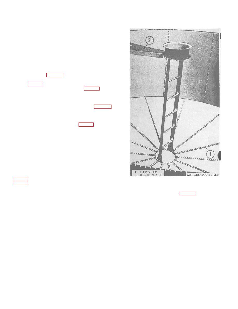
4-13. Installation of Ladder
a. Line up two diametrically opposite lap seams (1,
Figure 4-8. Center support ladder installed.
and left of each lap seam.
(8) over the bolts. Install and tighten nuts.
4-8
|
|
Privacy Statement - Press Release - Copyright Information. - Contact Us |
