 |
|||
|
|
|||
|
Page Title:
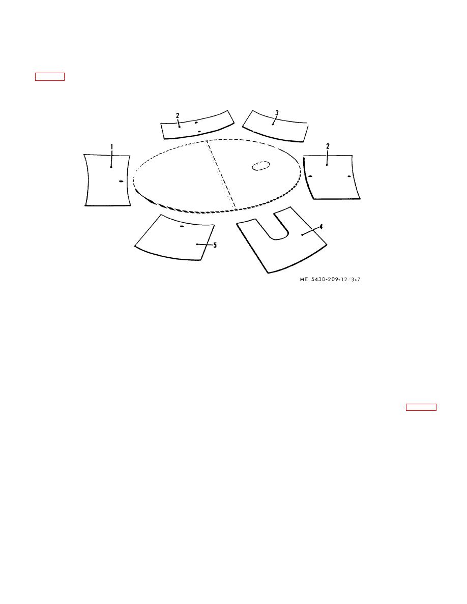
Figure 3-7. Layout of staves around tank bottom. |
|
||
| ||||||||||
|
|
 TM 5-5430-209-12
in preparing them for assembly. The staves are laid out
stave. This is to avoid having to lift them over the top of
the staves after assembly is completed.
so the first stave erected has vertical seam bolt holes on
left edge lined up with the bottom lap seam bolts.
(1) Layout of staves. Place staves (1 through
5, fig. 3-7) with the chimed side down for convenience
1.
6-INCH OUTLET STAVE
2.
3-INCH OUTLET STAVE
3.
GLAND STAVE
4.
CLEAN OUT STAVE
5.
4-INCH OUTLET STAVE
Figure 3-7. Layout of staves around tank bottom.
NOTE
(a) The end of the chime at the offset and
Staves have an offset at top and bottom
plain section, top and bottom, must be slightly bent for
The top is determined by looking at the
ease in installing. The ends of the chimes at the offsets
stave in a vertical position from the
must be bent inward (toward each other) (1, fig. 3-8).
outside In proper position, offsets are at
The ends of the plain chimes (2) are bent outward (away
the lower left and upper left corners (2)
from each other). The bends are made with a few sharp
Dressing staves.
blows from a hammer.
3-7
|
|
Privacy Statement - Press Release - Copyright Information. - Contact Us |
