 |
|||
|
|
|||
|
Page Title:
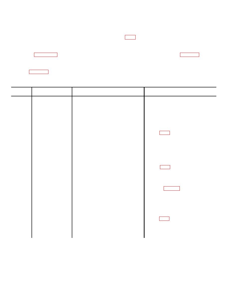
Table 7-3. Troubleshooting Intercommunication Switchboard SB-2601/G |
|
||
| ||||||||||
|
|
 TM 32-5895-227-14&P
indicates the proper jack location for stations 1 through
7-8
TROUBLESHOOTING SB -2601/G.
29 and the switch light indicator on the RICS.
a. General. Perform the procedures indicated
(2) Wiring diagram for SB-2601/G is shown
below for sectionalizing, localizing, and isolating trouble
in FO-6. This diagram outlines a complete electrical
to a particular circuit in the Intercommunication
means of performing maintenance on this unit. It
Switchboard SB-2601/G.
consists of connectors, switches, relays, and associated
b. Diagrams.
wiring.
(1) The location diagram for SB-2601/G is
shown in figure
There are 29 external
the trouble symptoms, the probable troubles, and the
intercommunication positions in AN/MSQ-71 which can
corrective actions to be taken
be transferred individually to any one of 10 channels on
.
RICS. Location of the transfer switches and relays are
shown in figure 7-4. Also, the rear view of SB-2601/G
Table 7-3. Troubleshooting Intercommunication Switchboard SB-2601/G
Item
Trouble symptom
Probable trouble
Corrective action
number
1
No power indication.
Burnt-out fuse (located at rear of
Remove and replace burnt-out fuse.
SB-2602/G)
Faulty electrical connections or wiring
Check power cable connections at
between SB-2601/G and SB-2602/G
connector J1 on SB-2601/G and J1 on
SB--2602/G. Check continuity and/or
voltage to SB-2601/G.
Defective power supply PS2 (located in
Refer to FO-6. Check 115 Vac input to
SB-2602/G)
power supply PS2 at terminal board
TB1.
Check for 20 Vdc at output. If no output,
power supply is defective. Remove and
replace faulty PS2 components as
required.
2
Inability to transfer
Defective station transfer switches S1
Refer to FO-6. Check for electrical
individual channels.
through S10
continuity and proper operation of station
transfer switches SI through S10.
Defective SB-2600/G
Troubleshoot suspected SB-2600/G as
3
Inability to transfer an
outlined in table 7-5.
individual station on
all channels.
Faulty electrical connections
Check cable connections at J5 of SB-
2600/G and J1 through J18 at OA-
7735/G to be sure they are secure.
4
Inability to transfer
Defective relays KI through K18 (located
Refer to FO-6 for presence of 20 Vdc at
an individual station
in OA-7735/G console)
relay coils K1 through K18. If 20 Vdc is
on a specific channel.
present and relay coil is not energized,
relay is defective. Remove and replace
relay.
7-9
|
|
Privacy Statement - Press Release - Copyright Information. - Contact Us |