 |
|||
|
|
|||
|
|
|||
| ||||||||||
|
|
 TM
9-2350-238-20-2
Failure
to
remove
or
disconnect
the
batteries
before
removing
or
installing
any
electrical wiring harness or lead may result in injury or damaged equipment.
Install
two
hexagon
capscrews
(1),
cab
signal
light
flasher
(2),
two
new
Iockwashers
(3),
1
and two hexagon plain nuts (4) on angle bracket (5).
Install utility outlet electrical lead (6), utility outlet cover (7), two new Iockwashers (8), and
2
two
machine
screws
(9)
on
angle
bracket
(5).
Install flasher indicator housing (10), two new Iockwashers (11), and two machine screws
3
(12) on angle bracket (5).
Install LED (13) in flasher indicator housing (10).
4
Install new
preformed
packing
(14)
on
flasher
indicator
light
(15).
5
Install flasher indicator assembly light lens (16) in flasher indicator light housing (10).
6
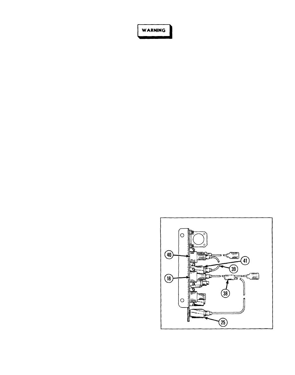
Install two machine screws (17), 30 amp circuit breaker (18), two new Iockwashers (19),
7
and two hexagon plain nuts (20) on angle bracket (5).
8
Install four machine screws (21), two 15 amp circuit breakers (22), four new Iockwashers
(23), and four hexagon plain nuts (24) on angle bracket (5).
Install 24 volt toggle switch (25), floodlight switch identification plate (26), two new
9
Iockwashers
(27),
and
two
machine
screws
(28)
on
angle
bracket
(5).
10
If
removed,
install
flasher
signal
switch
identification
plate
(29)
and
two
new
drive
screws
(30)
on
angle
bracket
(5).
11
Install 24 volt flasher signal toggle
switch
(31),
two
new
Iockwashers
(32),
and two machine screws (33) on angle
bracket (5).
Install
toggle
switch
(34),
level
wind
12
switch
instruction
plate
(35),
two
new
Iockwashers
(36),
and
two
machine
screws
(37)
on
angle
bracket
(5).
Install
and
connect
level
wind
switch
to
13
circuit
breaker
electrical
lead
assembly
(38) to 24 volt toggle switch
(25)
and
30 amp circuit breaker (18).
Install and connect circuit breaker to
14
floodlight switch electrical lead (39) to
15 amp circuit breaker (40) and 24 volt
toggle
switch
(41).
2-301
|
|
Privacy Statement - Press Release - Copyright Information. - Contact Us |