 |
|||
|
|
|||
|
|
|||
| ||||||||||
|
|
 TM
9-2350-238-20-2
NOTE
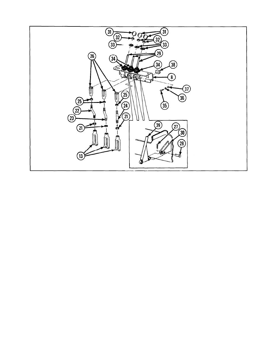
11 Remove three cotter pins (27) and three
Measure length center to center of
headed straight pins (28), releasing three
lower linkage controls prior to disas-
boom and tow winch manual control
levers (29) from mounting plates (30) of
sembly of clevises and nuts from
rods and shaft to assure accuracy
camlock controls support (8).
upon reassembly.
12 Remove
three
shift
lever
handle
knobs
Loosen
three
hexagon
plain
nuts
(21).
9
(31), three hexagon plain nuts
(32),
three tiedown straps (33), and
three
shift
Remove one end of two hydraulic valve
shift rods (22 and 23), and hydraulic
handle boots (34) from three boom and
tow winch manual control levers (29).
valve shift stud (24), and three hexagon
plain nuts (21) from three rod end cle-
Remove
three
boom
and
tow
winch
vises
(13).
manual control levers.
Loosen
three
hexagon
plain
nuts
(25).
13 Remove
two
hexagon
capscrews
(35),
10
Remove other end of two hydraulic valve
two
Iockwashers
(36),
two
flat
washers
shift rods (22 and 23), and hydraulic
(37), and winch control panel bracket
valve shift stud (24), and three hexagon
(38) from camlock controls support (8).
plain nuts (25) from three rod end
clevises (26).
2-131
|
|
Privacy Statement - Press Release - Copyright Information. - Contact Us |