 |
|||
|
|
|||
|
|
|||
| ||||||||||
|
|
 TM 9-2350-238-20-1
12
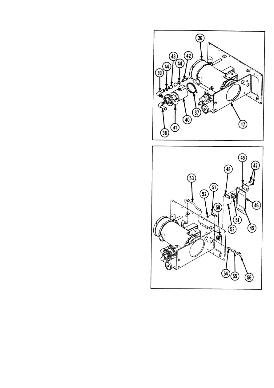
Install hose clamp (37) and two pipe to
hose elbows (38 and 39).
13
Install centrifugal pump unit (40) to coolant
heater mounting plate (17), and secure
with two nuts (41).
Install pipe to tube straight adapter (42) to
14
coolant heater assembly (26). Install
rubber hose (43) and two hose clamps
(44) to pipe to hose elbow (39) and
coolant heater assembly.
15
If removed, install coolant heater instruc-
tion plate (45) to access cover (46) with
adhesive.
16
Install access cover (46), and secure with
four machine screws (47). Install heater
control box cover hinge plate (48), coolant
heater control box cover butt hinge (49),
torsion heater control box cover helical
spring (50), two heater control box cover
spring retainers (51 ), and four new self-
locking nuts (52).
17
Install metal tube assembly (53), pipe
straight adapter (54), pipe coupling (55),
and drain cock (56).
2-1065
|
|
Privacy Statement - Press Release - Copyright Information. - Contact Us |