 |
|||
|
|
|||
|
Page Title:
MAINTENANCE OF PARKING BRAKE CONTROL AND LINKAGE. |
|
||
| ||||||||||
|
|
 TM 9-2350-238-20-1
2-140. MAINTENANCE OF PARKING BRAKE CONTROL AND LINKAGE.
c. Installation
a. Removal
This task covers:
d. Adjustment
b. lnspection/Repair
INITIAL SETUP
General Safety Instructions
Materials/Parts
Lockwasher
Lockwasher (4)
Self-locking nut
Brake foot pedal is spring-loaded.
Spring pin
Before working in driver's compart-
ment, block vehicle tracks and re-
References
lease parking brake.
TM 9-2350-238-24P-1
Equipment Conditions
2-938 Hull transmission compartment
deck assembly removed
2-820 Brake pedal, controls, and linkage
removed
REMOVAL
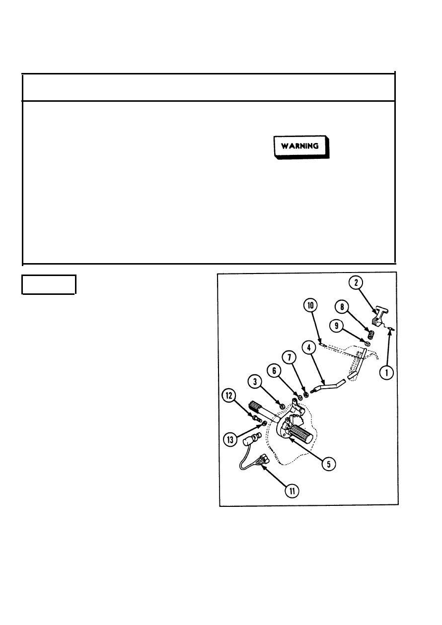
Remove spring pin (1) from brake handle
1
(2), and remove brake handle.
Remove self-locking nut (3) from parking
2
shoulder rod (4).
Remove parking shoulder rod (4) from
3
parking brake assembly (5).
Remove Iockwasher (6), hexagon plain nut
4
(7), helical spring (8), flat washer (9), and
headless grooved pin (10) from parking
shoulder rod (4).
Disconnect three electrical connectors (11)
5
of brake warning sensitive switch.
Remove four machine bolts (12) and four
6
Iockwashers (13). Remove parking brake
assembly (5).
2-814
|
|
Privacy Statement - Press Release - Copyright Information. - Contact Us |