 |
|||
|
|
|||
|
|
|||
| ||||||||||
|
|
 TM 9-2350-238-20-1
2-134. MAINTENANCE OF SHIFTING CONTROL AND LINKAGE (CONT).
ADJUSTMENT
1 Turn off engine.
2 Block tracks.
3 Shift transmission into first gear.
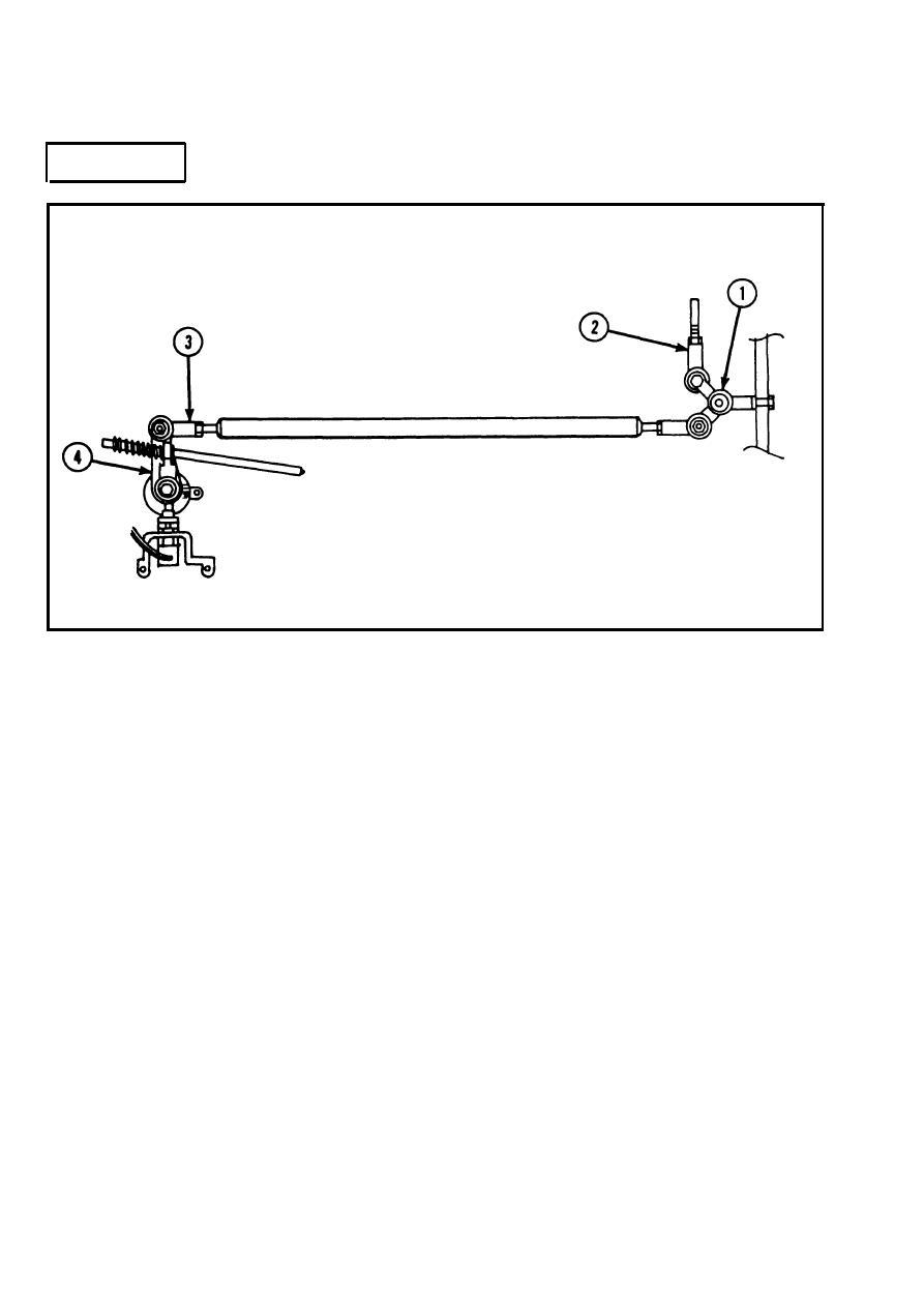
4 Measure distance from bulkhead to center of hole in upper lever of shift control linkage
bellcrank (1). Distance must be 1.56 to 1.69 in. (3.96 to 4.29 cm). If not, disconnect rod end
plain bearing (2) from shift control linkage bellcrank and adjust rod end plain bearing until
distance is within tolerance. Connect rod end plain bearing to shift control linkage bellcrank.
5 Check shift position indicator on transmission. Number 1 must be aligned with index hole. If
not, disconnect rod end plain bearing (3) from linkage shift control shift arm lever (4). Align
number 1 on indicator with index hole, as shown, then adjust rod end plain bearing until holes in
rod end plain bearing and linkage shift control shift arm lever are aligned. Connect rod end
plain bearing to linkage shift control shift arm lever.
6 Shift transmission through all positions. Stop at each position and check that shift position
indicator on transmission is aligned with index hole and agrees with driver shift control manual
control lever in driver's compartment.
7 Road test vehicle.
2-780
|
|
Privacy Statement - Press Release - Copyright Information. - Contact Us |
