 |
|||
|
|
|||
|
|
|||
| ||||||||||
|
|
 TM 9-2350-238-20-1
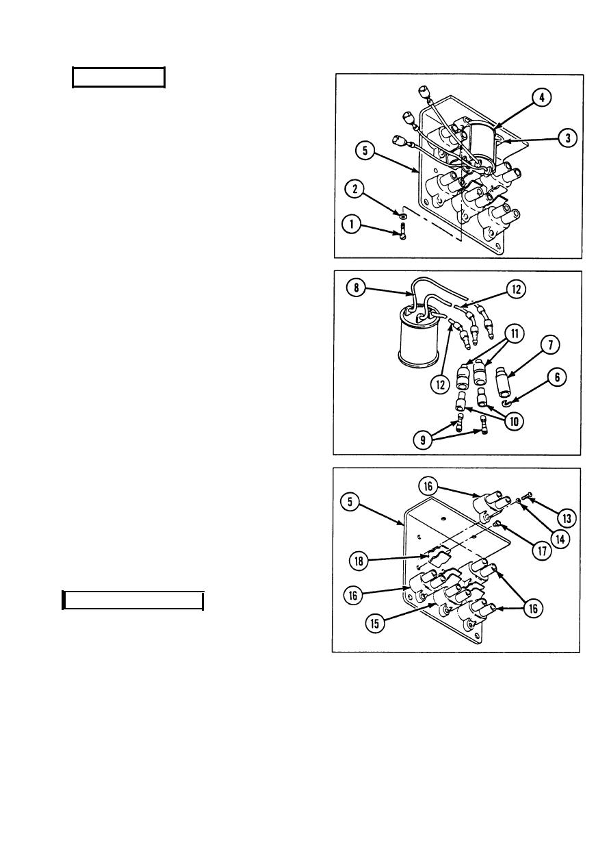
DISASSEMBLY
NOTE
Tag all electrical leads and cables
during disassembly to aid in
reassembly.
1 Remove two machine screws (1), two flat
washers (2), two rectifier mounting
brackets (3), and rectifier and lead (4)
from angle bracket (5).
2 Remove slotted washer (6) and electrical
shell (7) from attached electrical cable (8).
3 Remove two terminal assemblies (9), two
bushing insulators (10), and two electrical
shells (11) from two attached electrical
cables (12).
4
Remove ten machine screws (13), ten
Iockwashers (14), 20-amp circuit breaker
(15), and four 15-amp circuit breakers (16)
from angle bracket (5).
5
Remove three assembled washer screws
(17) and three spring tension clips (18)
from angle bracket (5).
INSPECTION/REPAIR
1 Inspect for broken, damaged, or missing parts.
2 Inspect rectifier for signs of overheating.
3 Inspect contact pin for corrosion.
4 Repair is by replacement of authorized parts (TM 9-2350-238-24P-1) which do not meet
inspection criteria.
2-591
|
|
Privacy Statement - Press Release - Copyright Information. - Contact Us |
