 |
|||
|
|
|||
|
|
|||
| ||||||||||
|
|
 TM 9-2350-238-20-1
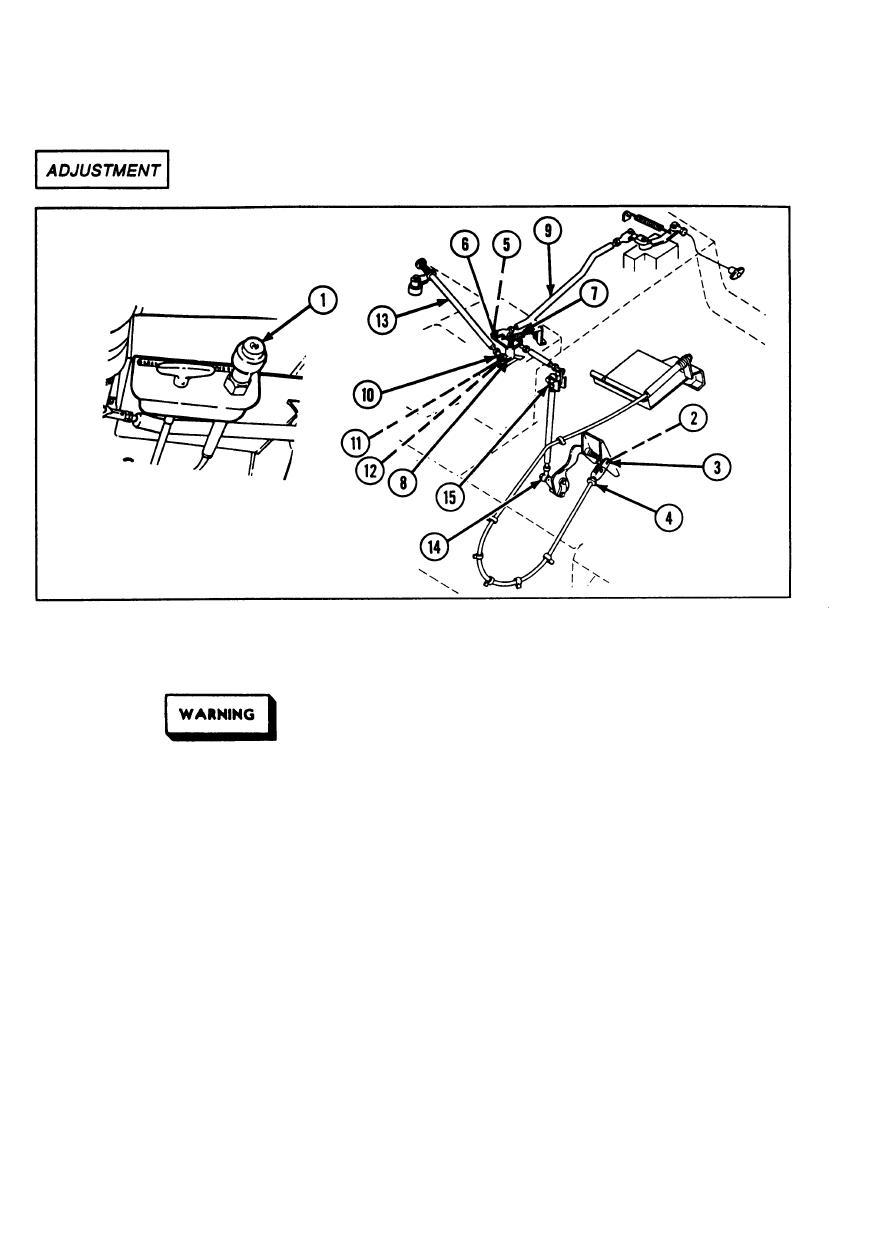
MAINTENANCE OF THROTTLE AND ACCELERATOR CONTROLS AND
2-56.
LINKAGE (ENGINE COMPARTMENT) (CONT).
8 Disconnect helical spring (7) from trans-
1 Turnoff engine.
mission and governor linkage bell crank
(8) .
2 Block tracks.
9 Position rigid connecting link (9) away from
transmission and governor linkage bell
crank (8).
Brake foot pedal is spring-loaded.
Before working in forward area of
10 Remove hexagon plain nut (10),
driver's compartment, ensure vehicle
Iockwasher (11), and hexagon head
tracks are blocked and parking brake
capscrew (12) from rod assembly (13) and
is released.
transmission and governor linkage bell
crank (8).
3 Release foot pedal.
11 Position rod assembly (13) away from
4 Push throttle control (1) in.
transmission and governor linkage bell
crank (8).
5 Remove cotter pin (2) and pin (3).
12 Adjust foot rigid connecting link rod ends
6 Remove clevis (4).
(14) to position vertical arm of throttle
linkage bell crank (15) parallel to bulkhead.
7 Remove cotter pin (5) and headed straight
pin (6).
2-508
|
|
Privacy Statement - Press Release - Copyright Information. - Contact Us |
