 |
|||
|
|
|||
|
Page Title:
MAINTENANCE OF THROTTLE AND ACCELERATOR CONTROLS AND LINKAGE (DRIVER'S COMPARTMENT). |
|
||
| ||||||||||
|
|
 TM 9-2350-238-20-1
2-55. MAINTENANCE OF THROTTLE AND ACCELERATOR CONTROLS AND LINKAGE
(DRIVER'S COMPARTMENT).
c. Installation
b. lnspection/Repair
a . Removal
This task covers:
INITIAL SETUP
Equipment Conditions
Matenals/Parts
2-938 Hull transmission compartment
Cotter pin
deck assembly removed
LockWasher (5)
2-935 Hull engine compartment deck
LockWasher (2)
assembly lid removed
Self-locking nut
References
TM 9-2350-238-24P-1
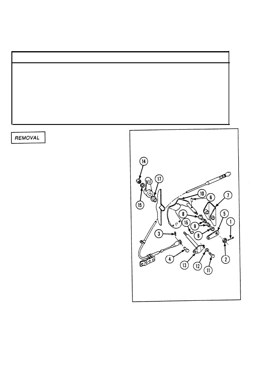
Remove cotter pin (1) and slotted plain nut
1
(2) .
NOTE
Use care not to lose or damage
cotter pin or pin.
Remove cotter pin (3), pin (4), and throttle
2
plate (5).
Remove spring pin (6), control pedal (7),
3
two sleeve bearings (8), and two helical
springs (9) from manual control lever (10).
Remove two hexagon head capscrews
4
(11) and two Iockwashers (12) from
accelerator shaft (13).
Remove self-locking nut (14) and flat
5
washer (15).
Remove machine key (16), accelerator
6
shaft (13), and sleeve bearing (17).
Remove manual control lever (10).
7
2-496
|
|
Privacy Statement - Press Release - Copyright Information. - Contact Us |