 |
|||
|
|
|||
|
|
|||
| ||||||||||
|
|
 TM 9-2350-238-20-1
23
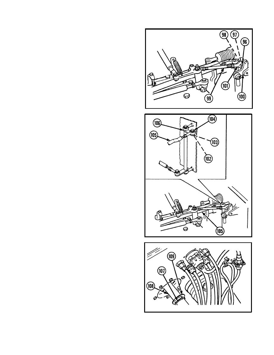
Remove hexagon plain nut (96),
Iockwasher (97), and hexagon head
capscrew (98) securing plain throttle
linkage stud (99) to throttle linkage bell
crank (100). Assemble hexagon head
capscrew, Iockwasher, and hexagon plain
nut to plain rod end bearing (101) to
prevent loss.
24 Remove hexagon plain nut (102), lock-
washer (103), and hexagon head cap-
screw (104) securing shift control rod
(105) to shift control linkage bell crank
(106). Assemble hexagon head capscrew,
lockwasher, and hexagon plain nut on shift
control rod to prevent loss.
25 Disengage retaining ring (107) from
groove in brake control shaft (108).
Remove retaining ring and ring spacer
(109), and slide brake control shaft into
driver's compartment.
2-393
|
|
Privacy Statement - Press Release - Copyright Information. - Contact Us |