 |
|||
|
|
|||
|
Page Title:
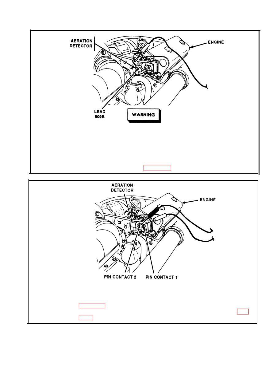
AERATION DETECTOR CIRCUIT. (Cont) |
|
||
| ||||||||||
|
|
 TM 9-2350-238-20-1
Make sure MASTER switch is OFF before repairing electrical
circuits. Failure to observe this warning could result in injury to
personnel.
Step 8.
Disconnect lead 509B from aeration detector. Place red probe on lead
509B. Ground black probe. Set MASTER switch ON. If multimeter
indicates about 24 volts, go to step 9. If multimeter indicates no voltage,
repair lead 509B. Refer to page 2-371. Set MASTER switch OFF.
Step 9.
Place red probe on aeration detector switch contact 1. Place black probe
on aeration detector switch contact 2. Coolant in radiators must be at full
level. If multimeter indicates 0 ohms, replace aeration detector. Refer to
aeration detector and low engine coolant level warning light. Refer to page
2-205
|
|
Privacy Statement - Press Release - Copyright Information. - Contact Us |
