 |
|||
|
|
|||
|
Page Title:
TRANSMISSION OIL PRESSURE INDICATOR CIRCUIT. (Cont) |
|
||
| ||||||||||
|
|
 TM 9-2350-238-20-1
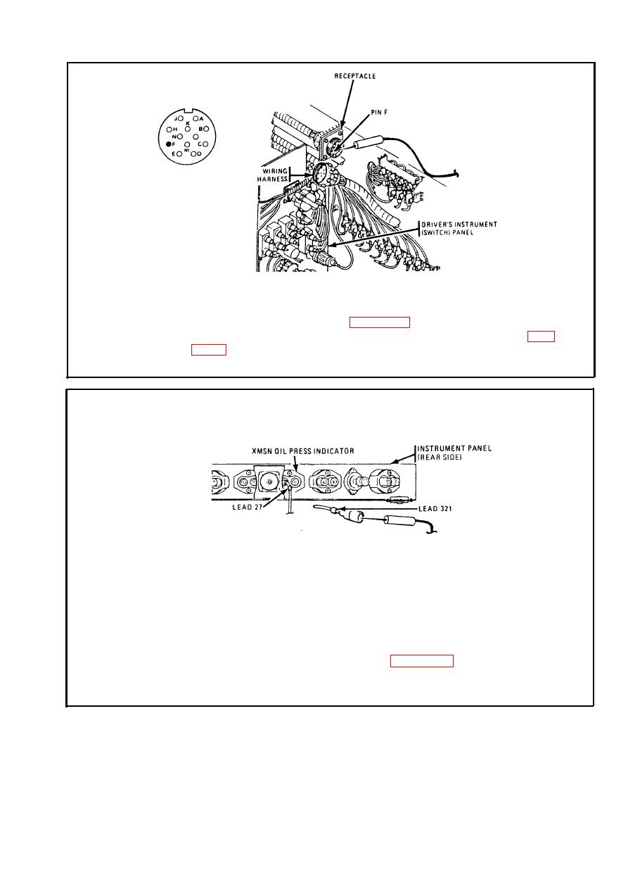
Step 2.
Disconnect wiring harness from instrument (gage) panel. Place red probe
on pin F (lead 27) of receptacle. Ground black probe. Set MASTER and
INST switches ON. If multimeter indicates no voltage, repair lead 27 from
INST switch to plug. Refer to page 2-371. If multimeter indicates about
24 volts, repair lead 27 from receptacle to instruments. Refer to page
instrument (gage) panel.
Disconnect lead 321 from XMSN OIL PRESS indicator. Place red probe in
Step 3.
lead 321. Ground black probe. Start engine and run at 1000 to 1200 rpm.
If multimeter indicates 0 ohms and does not increase, or increases to more
than 9 ohms, stop engine and go to step 4. If multimeter indicates 0 ohms
and then increases 4 to 9 ohms, increase engine rpm to 1800. Check
resistance and stop engine. If multimeter indicates 9 to 22 ohms, replace
XMSN OIL PRESS indicator. Refer to page 2-571. If multimeter indicates
less than 9 ohms or more than 22 ohms, go to step 4. Connect lead 321
to XMSN OIL PRESS indicator.
2-159
|
|
Privacy Statement - Press Release - Copyright Information. - Contact Us |
