 |
|||
|
|
|||
|
Page Title:
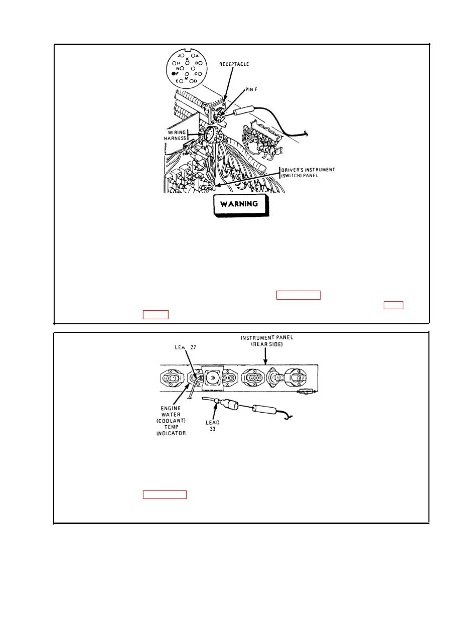
ENGINE COOLANT TEMPERATURE INDICATOR CIRCUIT. (Cont) |
|
||
| ||||||||||
|
|
 TM 9-2350-238-20-1
Make sure MASTER switch is OFF before repairing
electrical circuits. Failure to observe this warning
could result in injury to personnel.
Disconnect instrument (gage) panel wiring harness. Place red probe on
Step 2.
pin F (lead 27) of receptacle. Ground black probe. Set MASTER and
INST switches ON. If multimeter indicates no voltage, repair lead 27 from
INST switch to receptacle. Refer to page 2-371. If multimeter indicates
about 24 volts, repair lead 27 from plug to instruments. Refer to page
Start engine and run at 1000 to 1200 rpm for 15 minutes or until engine
Step 3.
reaches operating temperature. Stop engine. Disconnect lead 33 from
ENGINE WATER (COOLANT) TEMP indicator. Place red probe in lead
33. Ground black probe. If multimeter indicates between 900 and 1000
ohms, replace ENGINE WATER (COOLANT) TEMP indicator. Refer to
ohms, go to step 4. Connect lead 33 to ENGINE WATER (COOLANT)
TEMP indicator.
2-155
|
|
Privacy Statement - Press Release - Copyright Information. - Contact Us |
