 |
|||
|
|
|||
|
Page Title:
INSTRUMENT SWITCH CIRCUIT. (Cont) |
|
||
| ||||||||||
|
|
 TM 9-2350-238-20-1
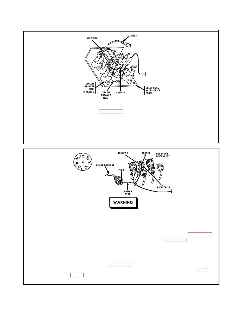
Step 4.
To access electrical accessories panel, remove left CO2 cylinder access
cover. Refer to page 2-923. Disconnect lead 27 from 20A circuit breaker
on electrical accessories panel. Place red probe in circuit breaker
terminal. Ground black probe. Set MASTER switch ON. If multimeter
indicates no voltage, go to step 6. If multimeter indicates about 24 volts,
go to step 5. Set MASTER switch OFF. Connect lead 27 to 20A circuit
breaker on electrical accessories panel.
Make sure MASTER switch is OFF before repairing
electrical circuits. Failure to observe this warning
could result in injury to personnel.
To access bulkhead disconnect, remove driver's seat, refer to page 2-952;
Step 5.
and remove driver's compartment aft cowl, refer to page 2-928. Discon-
nect wiring harness at bulkhead disconnect. Place jumper wire to pin D
and socket D (lead 459). Place red probe in socket C (lead 27) of
receptacle. Ground black probe. Set MASTER switch ON. If multimeter
indicates no voltage, repair lead 27 from circuit breaker to bulkhead
disconnect. Refer to page 2-371. If multimeter indicates about 24 volts,
repair lead 27 from bulkhead disconnect to INST switch. Refer to page
disconnect.
2-113
|
|
Privacy Statement - Press Release - Copyright Information. - Contact Us |
