 |
|||
|
|
|||
|
|
|||
| ||||||||||
|
|
 TM 9-2350-238-20-1
1-9. LOCATION AND DESCRIPTION OF MAJOR COMPONENTS (CONT).
c. Arm and hub assemblies. Roadwheel arm and hub assemblies are sprung by torsion bars
and lockout cylinders. The right and left rear arms (trailing idler arms) have an eccentric spindle that
permits moving the arm lengthwise to adjust track tension.
d. Lockout cylinders. Lockout cylinders serve as shock absorbers and bump stops. They can
be locked in position with hydraulic pressure to make a stable platform for lifting.
Torsion bars. Torsion bars absorb road shocks and provide vehicle spring support. Each
e.
torsion bar is connected to a roadwheel arm at one end and an anchor at the other end.
POWERPLANT
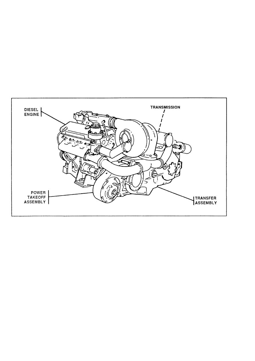
The powerplant consists of a diesel engine, transmission and transfer assembly, and power takeoff
assembly. The powerplant is removed-and installed as a unit. It must be removed before the
engine, transmission, transfer unit, and power takeoff can be separated. Engine power is transferred
to the transmission and power takeoff by the transfer assembly. Refer to TM 9-2520-234-35 for a
detailed description of the transmission and transfer assembly. Refer to TM 9-2815-202-24P for
engine breakdown and repair parts.
a.
Transfer assembly. The transfer assembly transfers engine power to the transmission and
power takeoff. The transmission transfers power through the final drives to the tracks. The power
takeoff transfers power through the auxiliary drive to the generator, fan, and hydraulic pumps.
Diesel engine. The engine is a General Motors 8V71T turbocharged 8-cylinder, V-type, 2-
b.
cycle diesel. Refer to TM 9-2815-202-34 for a detailed description of the engine.
1-10
|
|
Privacy Statement - Press Release - Copyright Information. - Contact Us |