 |
|||
|
|
|||
|
Page Title:
FRONT TUBE ASSEMBLY INSTALLATION |
|
||
| ||||||||||
|
|
 TM 9-2330-202-14&P
4-40.
HYDRAULIC BRAKE LINES REPLACEMENT (continued).
b.
FRONT TUBE ASSEMBLY INSTALLATION
1.
Install five loop clamps (2) on front tube assembly (4).
2.
Position front tube assembly (4) along curb-side drawbar (3) and connect to coupling (7).
3.
Connect front tube assembly (4) to connector (5) at master cylinder (6).
4.
Install five loop clamps (2) on curb-side drawbar (3) with five screws (1).
c.
REAR TUBE ASSEMBLY REMOVAL
1.
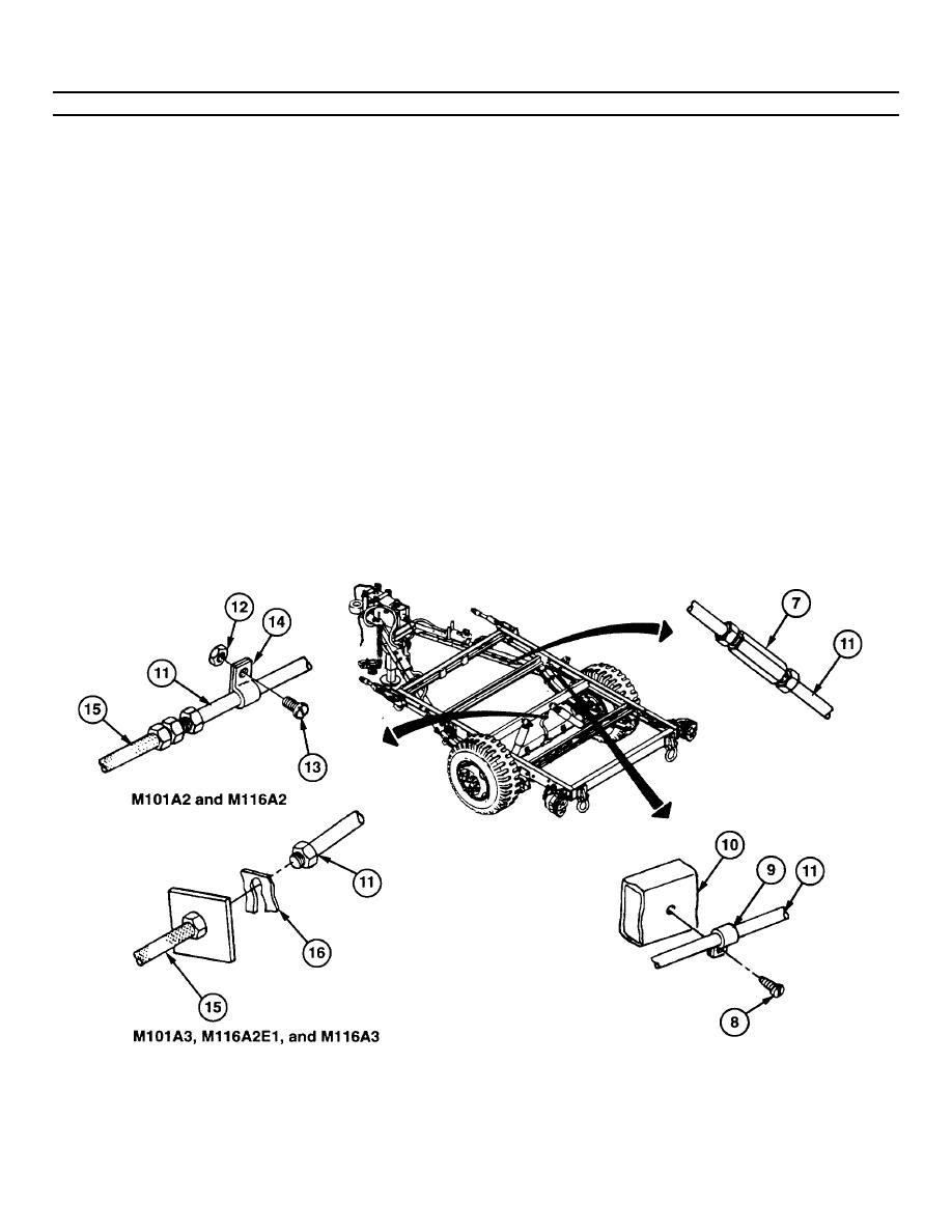
Remove two screws (8) from two loop clamps (9) along curb-side frame (10).
2.
Disconnect rear tube assembly (11) from coupling (7).
3.
On the M101A2 and M116A2, remove self-locking nut (12) and screw (13) from loop clamp (14) along crossmember.
Disconnect rear tube assembly (11 ) from hose assembly (15) and remove. Discard self-locking nut.
4.
On the M101A3, M116A2E1, and M116A3, remove rear tube assembly (11) from hose assembly (15) at retaining ring
(16).
5.On the M101A2 and M 116A2, remove two loop clamps (9) and loop clamp (14) from rear tube assembly (11).
4-77
|
|
Privacy Statement - Press Release - Copyright Information. - Contact Us |