 |
|||
|
|
|||
|
Page Title:
HYDRAULIC BRAKE ACTUATOR ASSEMBLY REPLACEMENT (CONTINUED) |
|
||
| ||||||||||
|
|
 TM 9-2330-202-14&P
4-38.
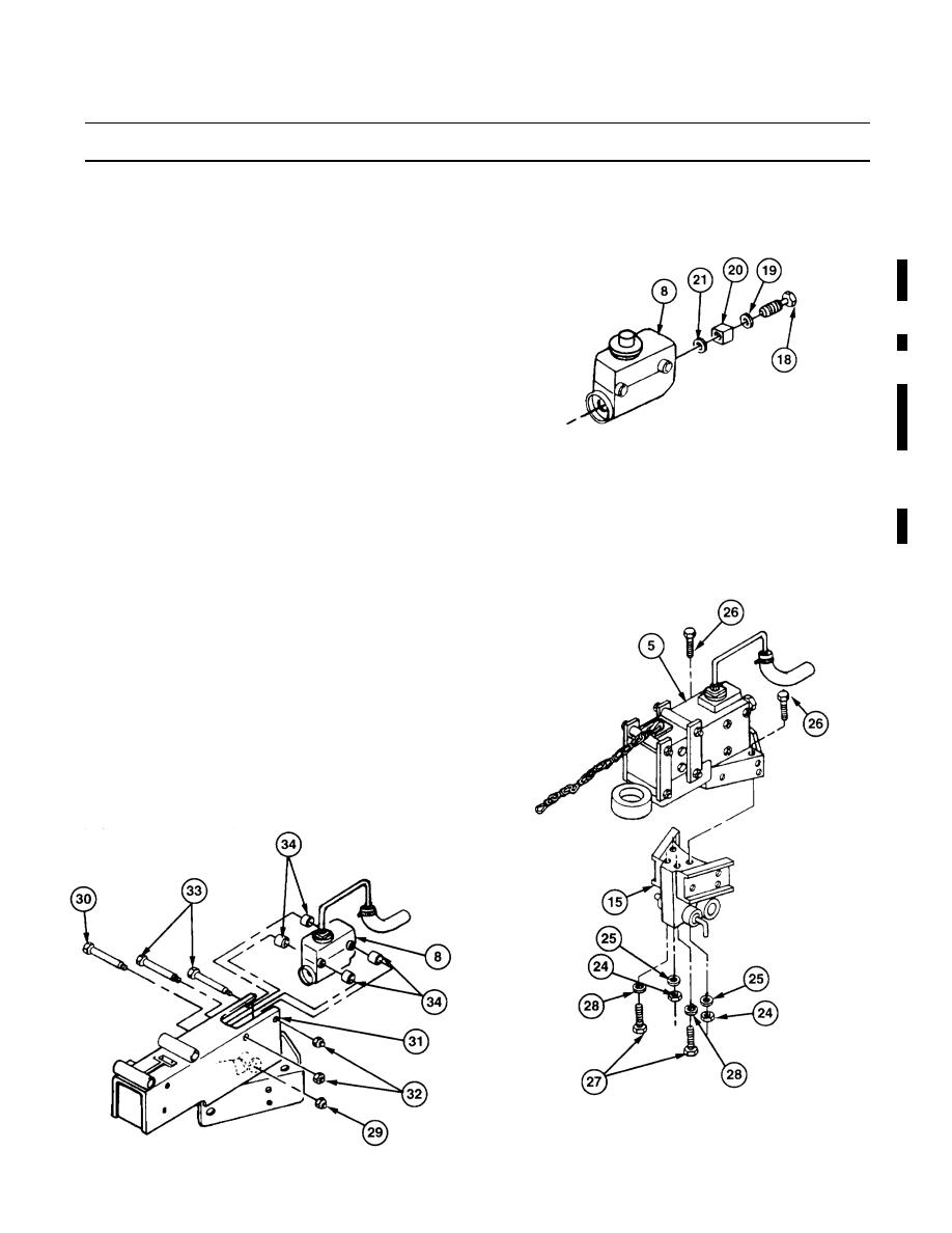
HYDRAULIC BRAKE ACTUATOR ASSEMBLY REPLACEMENT (CONTINUED).
7.
Remove fluid passage bolt (18), washer (19), connector (20), and washer (21) from master
cylinder (8).
8.
Remove four self-locking nuts (22) and
capscrews (23) from hydraulic brake
actuator assembly (5), drawbar bracket
assembly (15), and two drawbars (1).
Discard self-locking nuts.
9.
Remove drawbar bracket assembly (15),
with hydraulic brake actuator assembly
(5), from two drawbars (1).
10.
Remove two nuts (24), lockwashers (25),
and capscrews (26) from drawbar
438-081
bracket assembly (15) and hydraulic
brake actuator assembly (5). Discard
lockwashers.
11.
Remove two capscrews (27) and lockwashers (28) from drawbar bracket assembly (15), and
separate hydraulic brake actuator assembly (5) from drawbar bracket assembly (15). Discard
lockwashers.
b.
DISASSEMBLY
1.
Remove self-locking nut (29) and cap-
screw (30) from channel (31). Discard
self-locking nut.
NOTE
On newer-model trailers, spacers
are welded to inside of channel.
2.
Remove two self-locking nuts (32), cap-
screws (33), four spacers (34), and mas-
ter cylinder (8) from channel (31).
Discard self-locking nuts.
438-082
438-086
Change 2
4-65
|
|
Privacy Statement - Press Release - Copyright Information. - Contact Us |
