 |
|||
|
|
|||
|
|
|||
| ||||||||||
|
|
 TM 9-2320-360-20-2
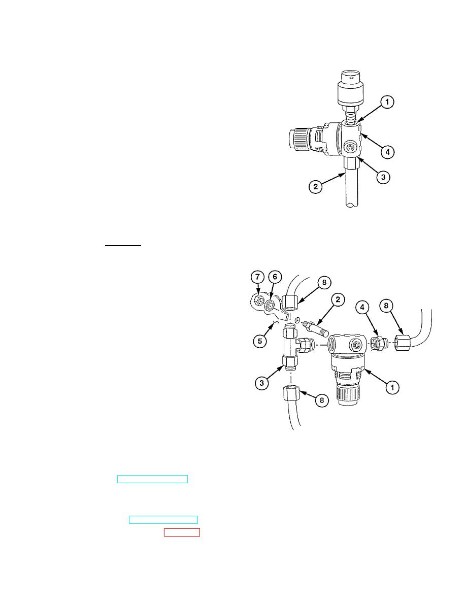
b. Adjustment
(1) Attach 0-1000 psi pressure transducer to
pressure regulator valve outlet port (1).
(2) Attach air supply hose (2) to pressure
regulator valve inlet port (3).
NOTE
Pressure regulator valve must be
adjusted to 70 psi (483 kPa).
(3) Adjust pressure regulator valve (4) to
proper air pressure using STE-ICE.
(4) Remove air supply hose (2) and pressure
transducer from pressure regulator valve (4).
c. Installation
(1) Install regulator valve (1) on stud (2).
WARNING
Pipe thread sealing compound can
burn easily, can give off harmful
vapors, and is harmful to skin and
clothing. To avoid injury or death,
keep away from open fire and use only
in well-ventilated areas. If pipe thread
sealing compound gets on skin or
clothing, wash immediately with soap
and water.
CAUTION
Use pipe thread sealing compound
sparingly only on pipe threads. Do not
apply compound at hose connections.
Damage to equipment may result.
(2) Coat threads of tee (3) and reducer (4)
with pipe thread sealing compound and
install on regulator valve (1).
(3) Install stud (2) on control console (5) with
new lockwasher (6) and nut (7).
(4) Connect hoses (8) to tee (3) and reducer (4).
d. Follow-On Maintenance
(1) Start engine (TM 9-2320-360-10).
(2) Build up air pressure to 120-125 psi (827-862 kPa).
(3) Check for leaks.
(4) Shut off engine (TM 9-2320-360-10).
(5) Install front console panel (para 17-8).
17-5
|
|
Privacy Statement - Press Release - Copyright Information. - Contact Us |
|
|
Integrated Publishing, Inc. - A (SDVOSB) Service Disabled Veteran Owned Small Business
|

