 |
|||
|
|
|||
|
|
|||
| ||||||||||
|
|
 TM 9-2320-360-20-2
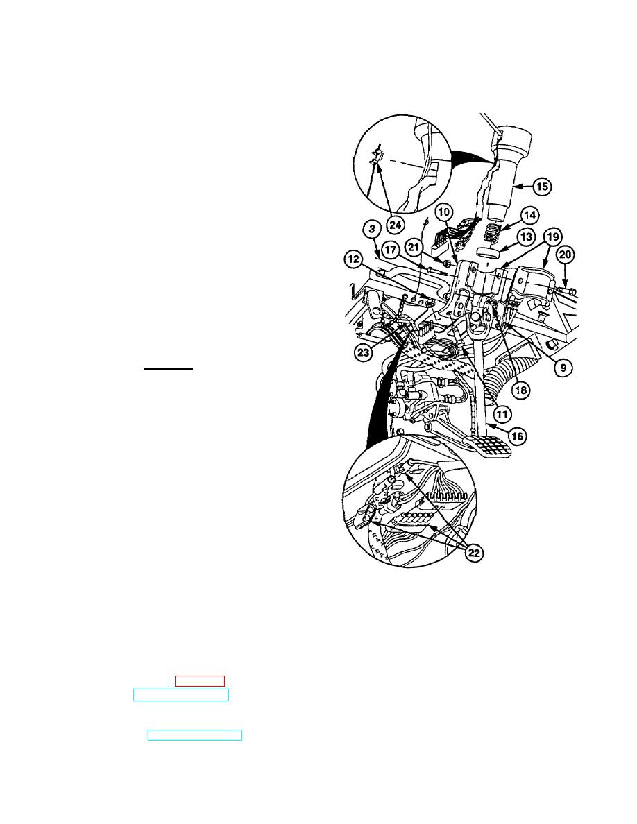
(4) Install left steering column lock br ace (9) and
right steering column lock brace (10) on dash (3)
with two screws (11) and new locknuts (12).
CAUTION
To install screw, hole in steering
column shaft must align with groove
in upper shaft.
Failure to install
screw through groove may result in
steering shaft disconnecting, causing
damage to equipment.
NOTE
Steering
column
is
properly
positioned when hazard control is on
right and turn signal lever is on left.
(5)
Install dust cap (13), spring (14), and steering
column (15) on upper shaft (16) with screw (17)
and new locknut (18). Torque to 35-40 lb-ft (47-
54 Nm).
WARNING
Do not overtighten steering column
mounting screws. Failure to tighten
them correctly can cause the steering
column to bind, resulting in loss of
steering control.
(6)
Install two rubber pads (19) on steering column
(15) with two screws (20) and new locknuts (21).
Torque to 85-100 lb-in (10-12 Nm).
(7)
Connect 1-pin, 2-pin, and 6-pin connectors (22).
NOTE
Plastic
cable
ties
should
be
positioned in locations marked
during removal.
(8) Secure connectors (22) with plastic cable ties
(23).
(9) Connect wire assembly ground clip (24) on
steering column (15).
c. Follow-On Maintenance
(1) Install steering wheel (para 13-2).
(2) Start engine (TM 9-2320-360-10).
(3) Check operation of steering (TM 9-2320-360-
10).
(4) Shut off engine (TM 9-2320-360-10).
Change 2 13-5
|
|
Privacy Statement - Press Release - Copyright Information. - Contact Us |