 |
|||
|
|
|||
|
|
|||
| ||||||||||
|
|
 TM 9-2320-269-34-1
TRANSMISSION SUBASSEMBLIES - CONTINUED
ACTION
LOCATION
ITEM
REMARKS
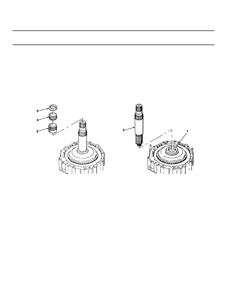
OUTPUT SHAFT INSTALLATION
76.
Low clutch ring
Output shaft (2)
Put in place.
gear hub (1)
77.
Output shaft (2)
Governor drive
Put on and engage spring pin.
gear (3)
78.
Speedometer drive
Put on.
gear (4)
79.
Spacer (5)
Put on.
REAR COVER ASSEMBLY INSTALLATION
80.
Adapter housing (6)
New rear cover
Put in place.
gasket (7)
81
Rear cover
Put in place.
assembly (8)
82.
Rear cover
Fourteen screws (9)
a. Screw in until snug, using 3/4-inch
assembly (8)
and washers (10)
socket and ratchet handle with 1/2-
inch drive.
b. Using 3/4-inch socket and torque
wrench with 3/8-inch drive, tighten
two screws (9) 180 degrees apart to
33 ft-lb (44.7 N m) of torque.
TA238409
2-674
|
|
Privacy Statement - Press Release - Copyright Information. - Contact Us |
