 |
|||
|
|
|||
|
Page Title:
INSPECTION/REPLACEMENT - CONTINUED |
|
||
| ||||||||||
|
|
 TM 9-2320-269-34-1
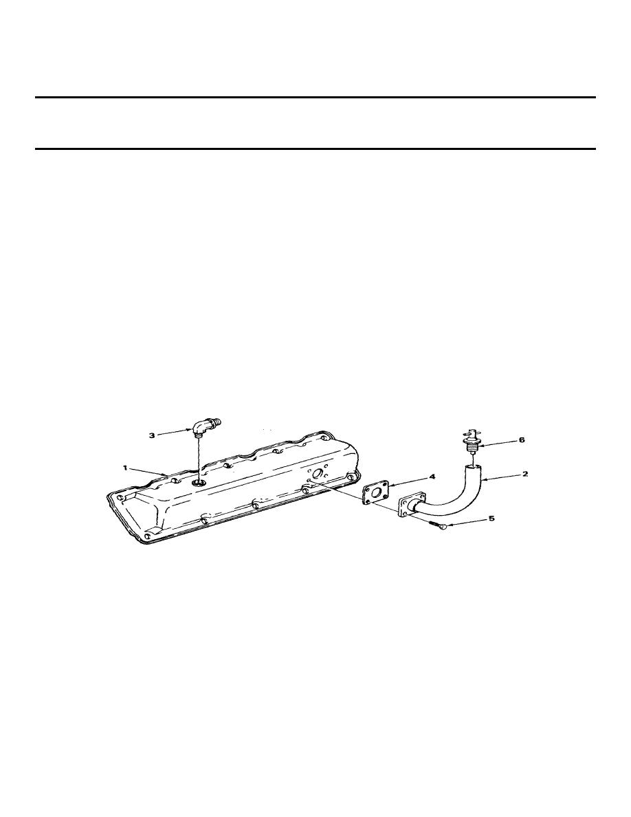
CYLINDER HEAD COVER ASSEMBLY - RIGHT SIDE - CONTINUED
ACTION
LOCATION
ITEM
REMARKS
INSPECTIONIREPLACEMENT - CONTINUED
11.
Cylinder head
Oil filler pipe
Look for dents, kinks, and sharp bends.
cover (1)
assembly (2)
12.
All threaded parts
Look for stripped and gouged threads.
ASSEMBLY
13.
Elbow (3)
Using 3/4-inch open-end wrench, screw In
tighten.
14.
New gasket (4) and
Put in position.
oil filler pipe
assembly (2)
15.
Oil filler pipe
Four screws (5)
Using 7116-inch socket and handle with
assembly (2)
318-inch drive, screw in and tighten.
16.
Oil filler cap (6)
a. Push in.
b. Screw in, and tighten.
c.
INSTALLATION
17.
Cylinder head (7)
New gasket (8)
Put in position.
and cylinder head
cover (1)
18.
Cylinder head
Ten new washers (9)
Screw in, and tighten using 3/8-inch
cover (1)
and screws (10)
flat-tip screwdriver.
TA238017
2-178
|
|
Privacy Statement - Press Release - Copyright Information. - Contact Us |