 |
|||
|
|
|||
|
|
|||
| ||||||||||
|
|
 TM 9-2320-269-34-1
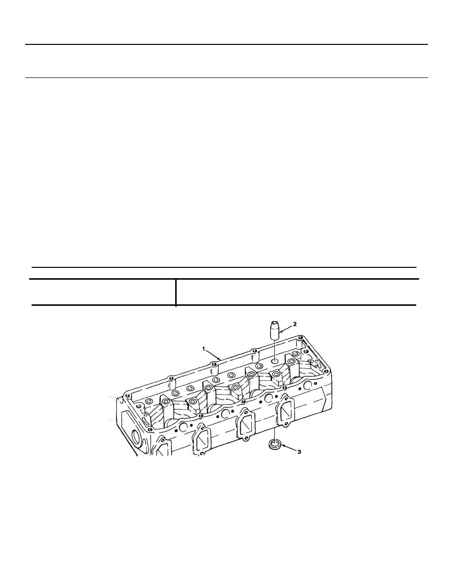
CYLINDER HEADS - CONTINUED
ACTION
LOCATION
ITEM
REMARKS
REPAIR - CONTINUED
22.
Continued
f.
Chill insert (3) thoroughly with dry
ice.
g.
Position insert (3) on installer tool
and using installer tool and 3-lb
ball-peen hammer, drive insert (3) into
head (1).
NOTE
Do not peen around injection nozzle area or on intake valve insert.
h.
Using 1/4-inch blunt end drive-pin
punch and 3-lb ball-peen hammer,
peen head (1) metal over outer edge
of insert (3).
i.
Using valve seat grinder, reface
insert (3).
Use chart below for specific angle
and seat width. During grinding
operation, take off the minimum
amount of material necessary to t
up the insert.
INTAKE AND EXHAUST VALVE SEAT INSERTS
FACE ANGLE
45 degrees
SEAT ANGLE
45 degrees
SEAT WIDTH
0.080 - 0.090 inch 2.03 - 2.29 millimeter
TA237974
2-109
|
|
Privacy Statement - Press Release - Copyright Information. - Contact Us |
