 |
|||
|
|
|||
|
|
|||
| ||||||||||
|
|
 TM 9-1375-213-12-1
Figure 2-5.
Erecting tripod.
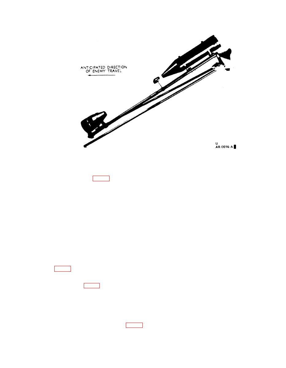
(6) Step back about 10 feet (3.0 meters) and
the launch leg is pointed in the direction
check alignment of components on launch leg. If
of the enemy travel (fig. 2-6).
components are not aligned, attempt improve-
c. The rocket motor may be assembled to the
ment by using the hex socket head wrench which
warhead prior to erecting the tripod by following
is taped to one of the legs to change the position
the procedures in f below, prior to proceeding to
of the upper bracket holding the shaped charge
d.
to the launch leg.
d. Using base of launch leg as a pivot, and stand-
2-5. Preparing Field Firing Lead
ing at rear of warhead, raise tripod and pivot sup-
port legs outward as far as possible.
NOTE
e. Keeping support legs fully extended, tilt tri-
Make sure electrical wire splices are se-
pod backward until support legs meet ground. To
curely twisted together. Use at least two
avoid accidental toppling of tripod, assure that
inches of bared conductor from each wire
restraining wires are taut and legs are firmly po-
end being spliced. Insulate each conduc-
sitioned on ground.
tor splice with tape to prevent shorting.
f. Mount each rocket motor as follows:
a. Lay field firing lead (electrical
(1) Unlatch peripheral clamp holding protec-
power cable or type WD-1/TT telephone
tive disk on warhead by pulling on the nylon cord
cable) from kit (s) to firing location.
loop (A, fig. 2-7).
To prevent accidental toppling of the
(2) Remove protective disk and put it in ship-
M180 kit due to pulling or tripping on
ping container; leave clamp on warhead.
the firing lead, wind field lead around
(3) Align ring (B, fig. 2-7) of rocket motor with
a stake or other object secured to the
mating groove on rear of warhead flange. Insert
ground.
ring into groove and insure that clamp is over both
rocket and warhead flanges.
b. Short circuit firing lead Conductors at firing
(4) Rotate rocket motor so that continuity plug
(blasting machine) location.
and yellow-tagged safety plug are on top.
c. At kit location, check firing lead with galva-
nometer or Blasting Cap Test Set M51. If a gal-
(5) Hold peripheral clamp in place and snap
vanometer is being used, about 23 ohms should he
shut to secure rocket motor to warhead (fig. 2-8).
2-7
Change 3
|
|
Privacy Statement - Press Release - Copyright Information. - Contact Us |
