 |
|||
|
|
|||
|
Page Title:
BOTTOM HOUSING ASSEMBLY AND RELATED PARTS DISASSEMBLY |
|
||
| ||||||||||
|
|
 TM 9-1290-335-34&P
4-27.
BOTTOM HOUSING ASSEMBLY AND RELATED PARTS DISASSEMBLY
TOOLS:
1/8" and 5/16': drive pin punch
1/4" flat tip screwdriver
Machinist scriber
5/32" socket head screw key (Allen wrench or equivalent)
4 oz. ball peen hammer
PERSONNEL: One
EQUIPMENT CONDITION: Azimuth indicator on work bench
FRAME 1
Step
Procedure
1.
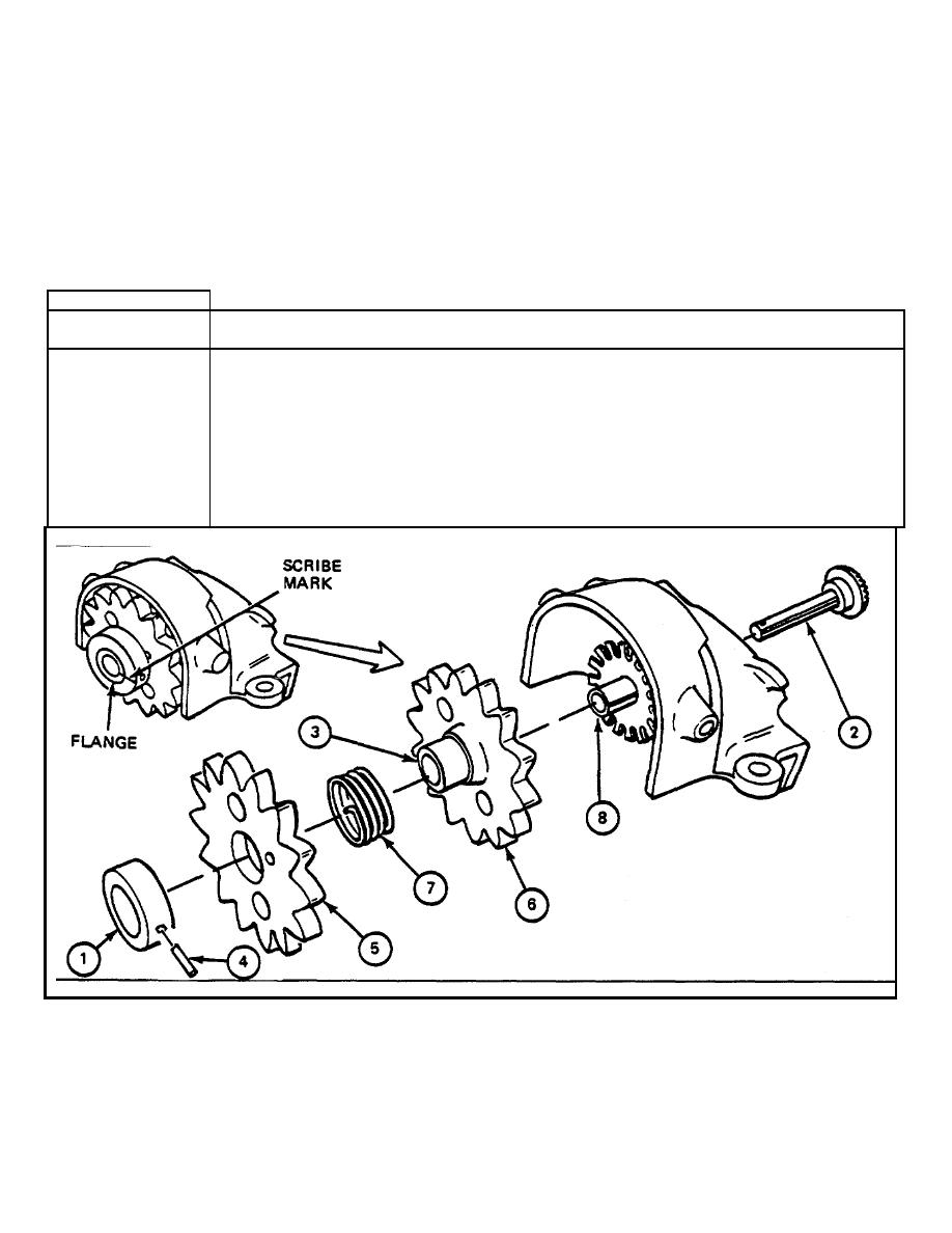
Using scriber, draw a scribe mark on collar (1), shaft (2), and flange (3).
2.
Using 5/16" punch and hammer, drive out pin (4) far enough to remove collar (1). Remove collar.
3.
Remove anti-backlash gear assembly (5), (6) and (7) from shaft (2).
4.
Slide shaft (2) out of sleeve bearing (8).
5.
Using screwdriver, disassemble anti-backlash gear assembly by prying apart gears (5) and (6) and
spring (7).
6.
Look at pin (4), gears (5) and (6) and torsion spring (7). If gears (5) and (6) are changed in shape
or have missing or broken teeth, replace gear. If pin (4) or torsion spring (7) is changed in shape,
replace pin or spring.
GO TO FRAME 2
Vol II
Para 4-27
4-35
|
|
Privacy Statement - Press Release - Copyright Information. - Contact Us |