 |
|||
|
|
|||
|
Page Title:
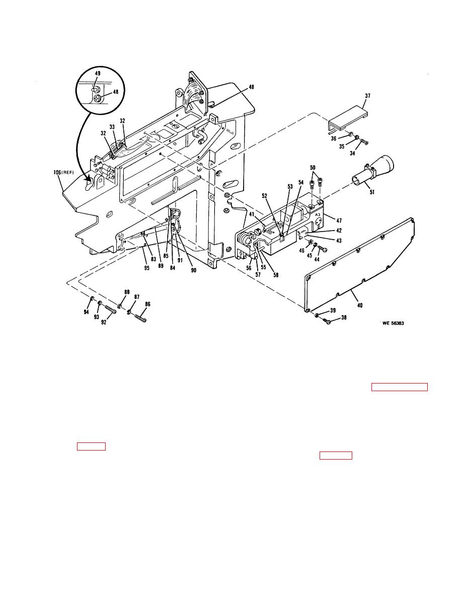
Figure 3-6. Disassembly of Laser Receiver-Transmitter RT-1021/VVG-1 (A76) (Sheet 3 of 3 sheets) |
|
||
| ||||||||||
|
|
 TM 9-1240-369-34
Figure 3-6. Disassembly of Laser Receiver-Transmitter RT-1021/VVG-1 (A76) (Sheet 3 of 3 sheets).
(5) Lubricate new ballistic cover gasket (6) by
components that are replaceable on
applying a thin, uniform, film of grease, MIL-G4343, to
the optical bench assembly.
the high point on the bead of the gasket. Do not apply so
(1) Remove ballistic cover assembly and
much grease that it fills the grooves on either side of the
ballistic cover gasket as instructed in paragraph 3-12 a,
bead. Apply by hand to the inserts on both sides of the
steps (1) thru (4).
ballistic cover gasket.
(2) Remove 10 screws (7), 10 washers (8),
(6) Install new ballistic cover gasket (6) by
and access cover (9).
performing step (4) in reverse order. Use new screws
(3) Cut lockwire (10) between retaining nut
(31 and torque to 45 to 50 inch-pounds.
(11) on connector A76J3 (12) and screw (13).
b. Removal and Installation of Optical Bench
(4) Remove retaining nut (11) which secures
Assembly (see fig. 3-6).
connector A76J3 to housing assembly (106) with
connector wrench (15, table 2-1).
NOTE
(5) Loosen two captive screws on screw
locking assembly (14) and disconnect connector
The optical bench assembly as a
A76W1P3 (15).
whole is not a replaceable assembly.
This assembly must be removed from
WARNING
the main housing assembly in
Ethyl alcohol is flammable. When
accordance
with
the
following
using it for cleaning, keep it and all
procedure in order to replace the
flammable cleaning materials away
from open flames.
3-19
|
|
Privacy Statement - Press Release - Copyright Information. - Contact Us |